
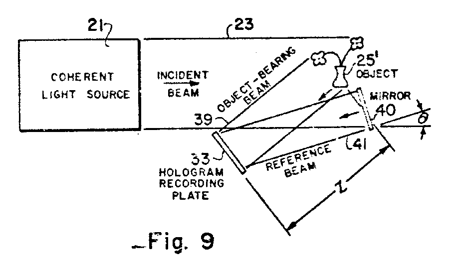
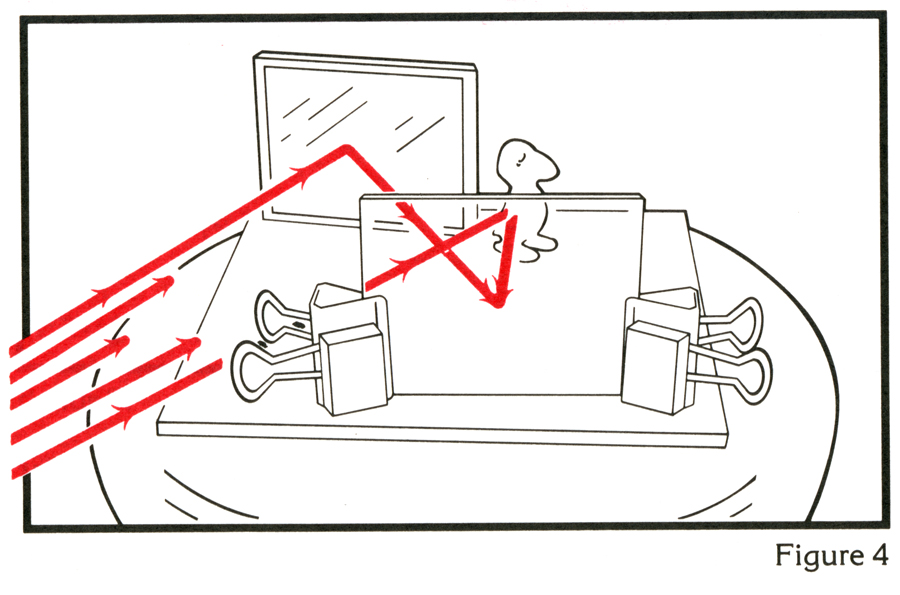
Holography didn’t become viewer friendly until the introduction of the off-axis reference beam scheme by Leith and Upatnieks, which pointed the reconstructing light out of the line of sight of the viewers eyes. They graduated from holographing backlit transparencies, not unlike Gabor but with some major improvements, (see Project 1b), to front-lit diffusely reflecting objects, simply by placing a mirror next to an object. The mirror reflected the unmodulated coherent waves directly to the Hologram Recording Plate to interfere with the object beam to produce the holographic interference pattern. Here is a sketch of the scheme as depicted in United States Patent Number 3,506,327 (filed April 23, 1964, received April 14, 1970),
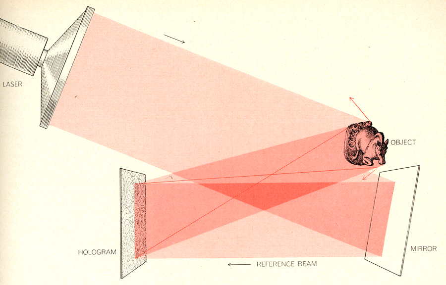
and possibly made clearer in this illustration in Photography by Laser in Scientific American of June 1965,
and finally a picture of Emmett and Juris with such a set up.
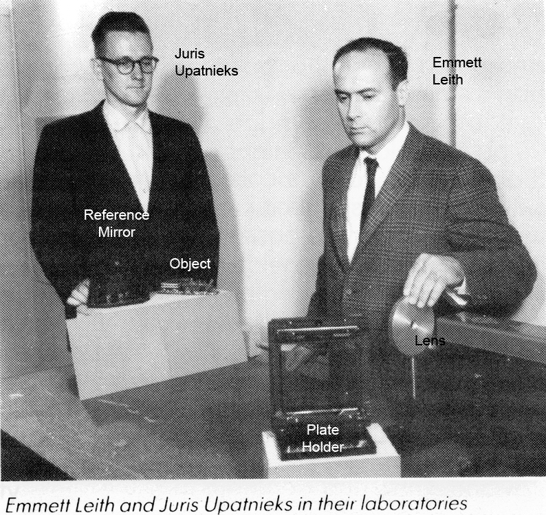
Emmett is adjusting the beamspreading lens, and Juris is adjusting the mirror to reflect light directly to the holographic plate in the plateholder.
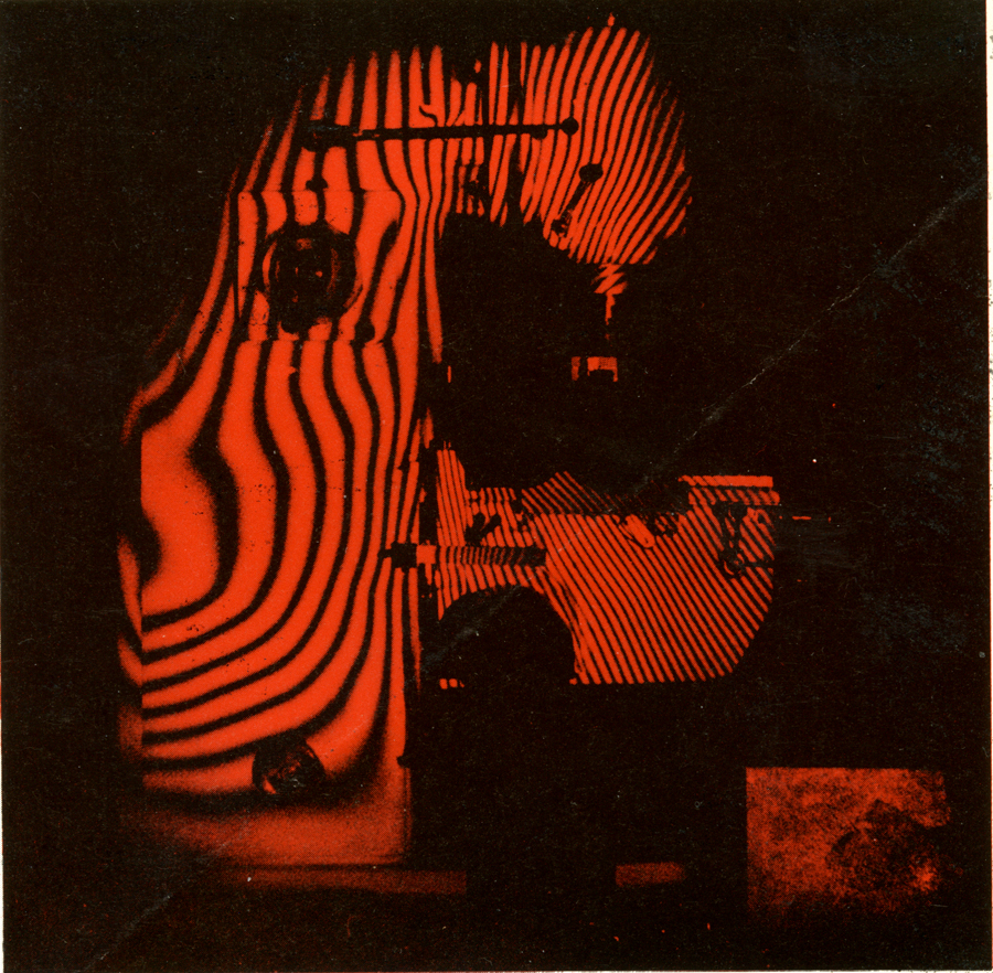
Probably one of the boldest implementations of this set up is credited to Nils Abramson, who recorded holograms of a 2 meter tall milling machine on a factory floor, using only a 50 mW laser! The diverging laser beam traveled some 10 meters and completely illuminated the machine, and a small mirror was placed next to it to reflect light back to the holo-plate for the reference beam. The fringes on the object are for the diagnosis of deformation. (For the full story, see N. Abramson, Sandwich hologram interferometry, 4: Holographic studies of two milling machines, Applied Optics 18, 2521 (1977), or The Making and Evaluation of Holograms, Nils Abramson, Academic Press, 1981, ISBN 0-12-042820-2, or this LaserGruppen Holovision flyer.)
It is for this reason that the proof of concept hologram for this set up is called Nils's Dice.
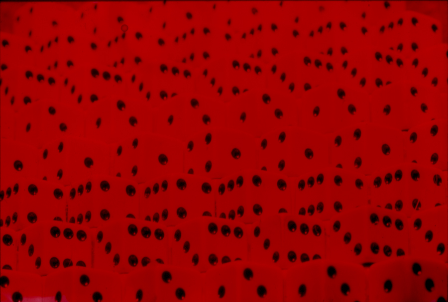
The spreading beam travels from the left and is big enough to cover the reference mirror and the object.
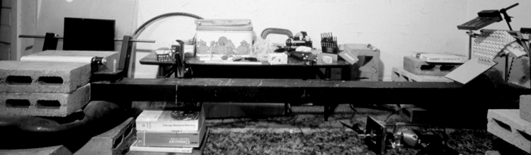
The set up is upside down for maximum stability; the reference mirror rests on bricks hot-glued to the beam, and the dice are attached to the goalposts at the tee end of the beam, and in turn resting on the reference mirror so that they would move together if they moved during exposure. and the plateholder is attached to the dice's base.
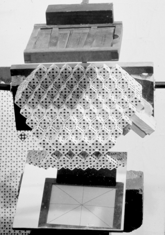
This is the point of view from the beamspreader, who sees the holographic plate in its plateholder by way of the mirror.
If this configuration of the set up seems to be a bit awkward, try builiding it so the reference comes from the side, as TJ demonstrated in the Edison book.
Here is the classroom handout with step by step instructions I had written for making this set up in the sandboxes of Gallery 1134, and here are a couple of handouts to do the same on the metal tables at the School of the Art Institute of Chicago. And here is a study the author did in the spirit of Abramson on evaluating holographic plateholders.
BIBLIOGRAPHY:
E. N. Leith, J. Upatnieks, "Wavefront Reconstruction with Diffused Illumination and Three-Dimensional Objects", Journal of the Optical Society of America, Volume 54, Number 11, November 1964, p. 1377.
E. N. Leith, J. Upatnieks, "Photography by Laser", Scientific American, Volume 212, Number 6, p. 24, June 1965
E. N. Leith, J. Upatnieks, "Wavefront Reconstruction Photography", Physics Today, p. 26, August 1965
<back PROJECT 3: Division of Amplitude Holograms next>
<Introduction> <Equipment> <The Big Beam> <Project 1a: In-line "Gabor" type Holograms> < Project 1b: Off-Axis Holograms> < Project 2: Single Beam Transmission Deep Scene Hologram> <Project 3: Division of Amplitude Hologram> <Project 4: Pseudo-Achromat Transfer Hologram> <Project 5: Cylindrical Hologram> <Project 6: Single Beam Reflection Hologram> <Project 7: Image Plane Reflection Hologram> <Bonus Project 1: Diffraction Gratings> <Bonus Project 2: Holoroids>