I had out-grown my original sandbox. If I wanted to make bigger than 2 ¼” square holograms I needed more throw. Plus Tuffy the Cat had some devious interest in it.
TJ (Tung Jeong) had mentioned in a lecture that he had seen in Russia an optical rail that had been made from a pair of railroad rails welded together, side by side. What more do you need for single beam work? Just a long, unimpeded throw.
Hans Bjelkhagen claims that possibly TJ was a bit confused about where he had seen this iron beam, as Hans and Nils Abramson had made the beam out of a pair of I-Beams welded together at the Royal Institute of Technology. Hans has promised to send a picture of this device sooner or later. But that doesn't discount the possiblility that there may have been some sort of a device like this in Russia.
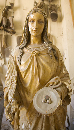
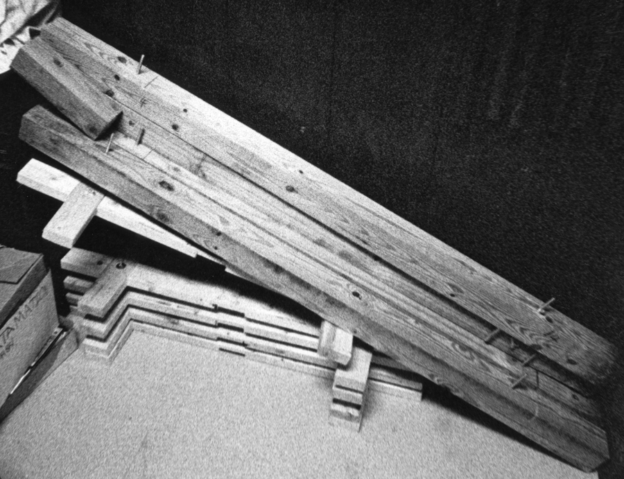
My good friend Larry Zgoda, stained glass artist extraordinaire had scrounged up a 4” by 6” by 6’ wooden beam from a rehab job he was working on at Notre Dame de Chicago. (He mentioned that he ran across a statue of St Lucy in its basement, quite gruesome, but fitting for holographers, as the root of her name comes from the Latin, lux, for light. No wonder I grew up to be somewhat of a nut case being exposed to iconography like this!)
Larry and I took the piece of lumber to Chicago Millman's, a woodworking shop that was open on Saturday, as the owner had his children there learning the trade, and proceeds for the day went directly to their college fund. I put a sawbuck in the tip jar after the beam was planed to perfection.
Although some might balk at wood being used for something as critical as an optical rail, let me remind you that the Mutiplex machines of Lloyd Cross were wood and particle board. But wood is quite strong, hold up floors of buildings!
Although it is not as dimensionally stable as metal, take a look up at an unfinished ceiling and you will see huge beams on the scale of the Big Beam holding up the floor above. A laser, beamspreader and object are nowhere near as heavy as floorboards.
Wood’s biggest enemy is humidity, so a good coat of varnish is necessary, polyurethane preferred, and then a nice coat of paint. A pair of handles could be attached to the side for easy portability.
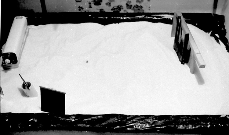
The first incarnation of the Beam utilized only 2 inner tubes, one at each end of it. Here is the first published picture of it, from How to Make Holograms, by Don McNair,Tab Books, 1983, ISBN 0-8306-0109-0 with a Spectra-Physics Model 124 Helium Neon 15 mW laser mounted on it. Don himself took the picture at the party I threw on the Saturday before the 1982 ISDH. The room was full of people, who obliged his request to take an uncluttered picture of it.
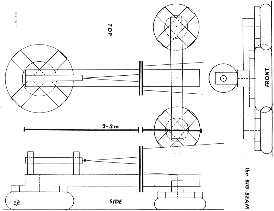
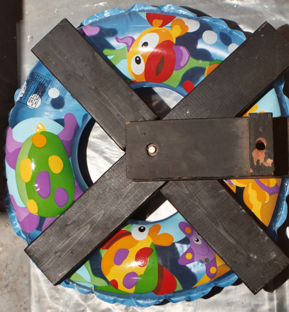
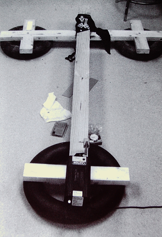
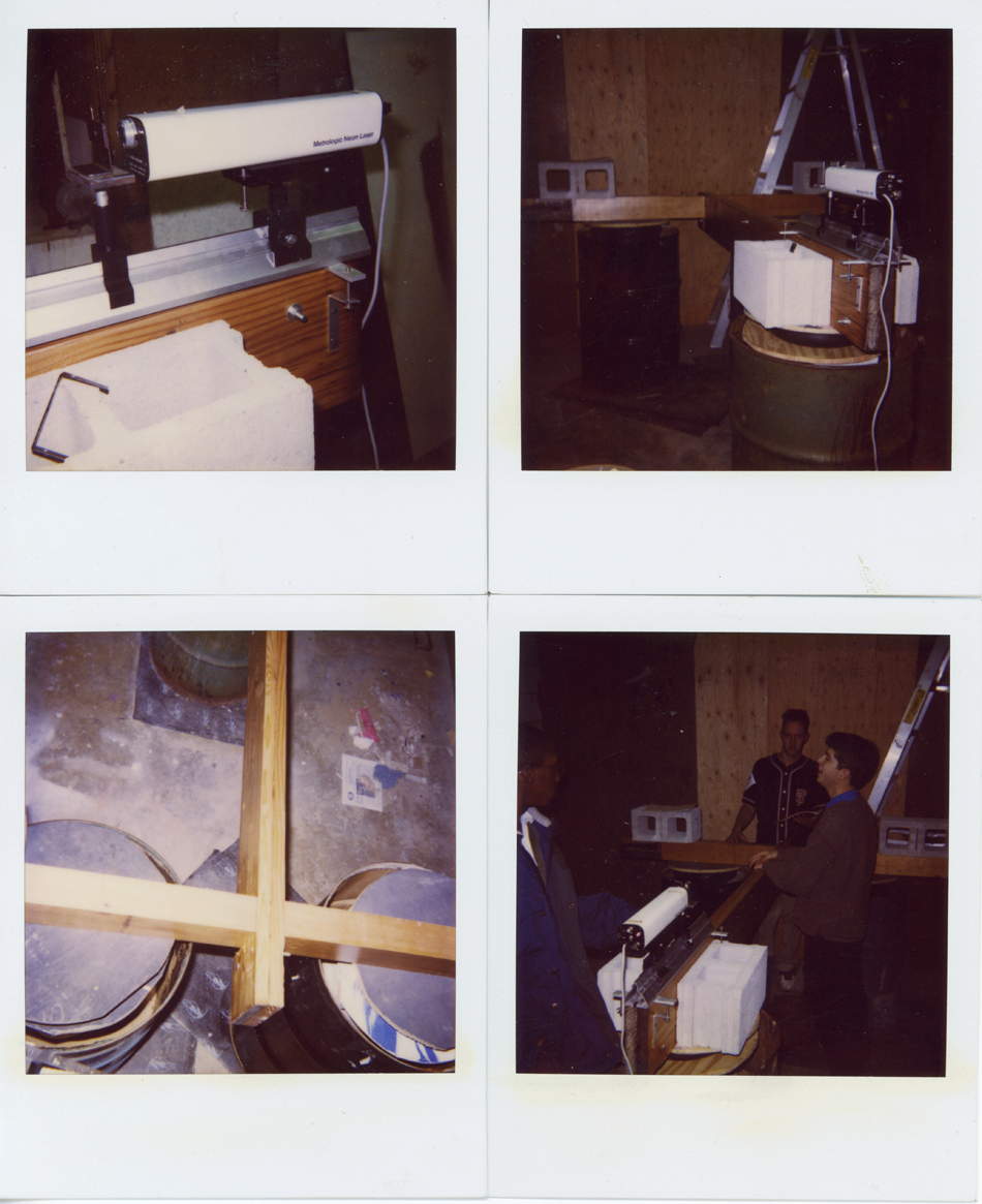
Two tubes did not provide a stable platform, as it had a tendency to roll from side to side. Three points determine a plane, so another tube was added as the Beam morphed into something more cruciform. (Catholic upbringing rears its head yet again!) One larger inner tube was under the laser end, while two smaller ones were on either side of the cross bar. Wooden X shapes sit under the beam on top of the tubes. It is all screwed together with carriage bolts and wing nuts for easy set up and tear down for storage and transportation, as shown in this sketch below.
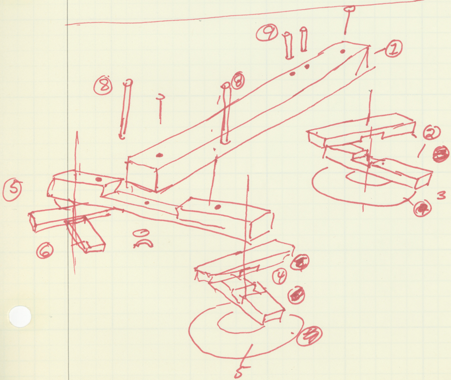
Not many vehicles use inner tubes anymore, so they are hard to find, even at automotive tire dealers. Places like Blain’s Farm and Fleet or similar stores that service the agricultural market still carry them on their shelves. But you can see in the photos above that even a swimming pool accessory is strong enough to support and isolate the Beam.
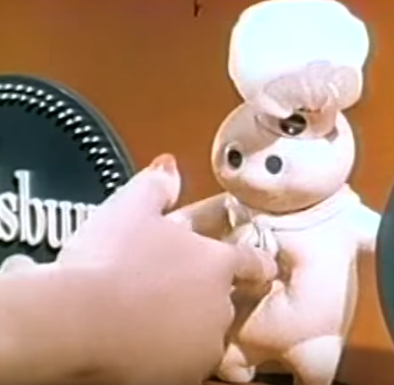
The inner tubes do not have to be highly inflated, just enough to get the beam off the ground. If a finger is poked into it, it should behave like the Pillsbury Dough Boy.
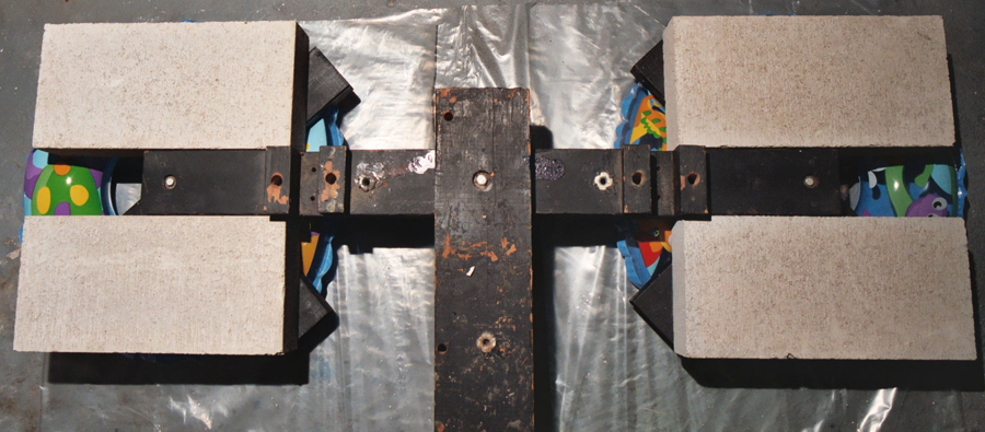
Cinder blocks on the X-es give more mass to combat vibrations, and provide a working space for optics and tools.
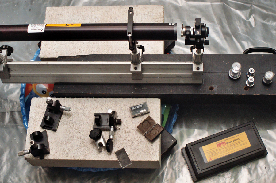
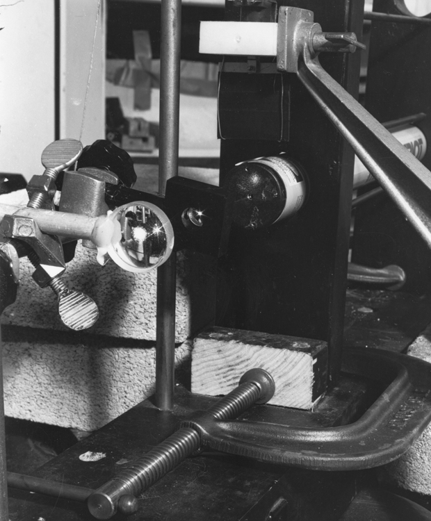
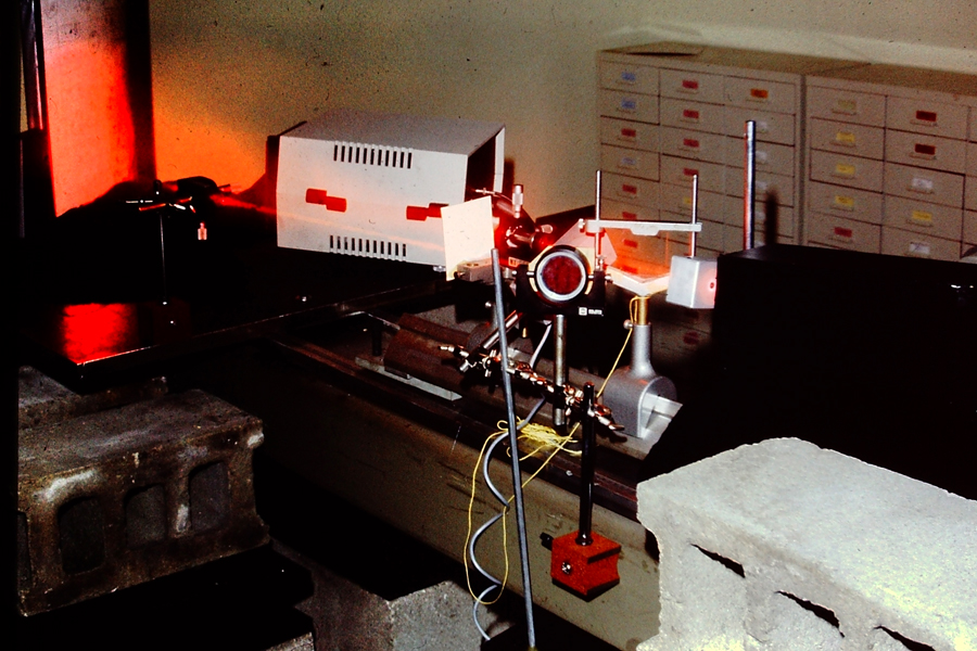
Holes are drilled into the beam for ½” diameter rods to attach optics and objects to the beam. Here are a couple of negative lenses used as beam spreaders clamped with right angle clamps onto the vertical rods sunk into the wood.
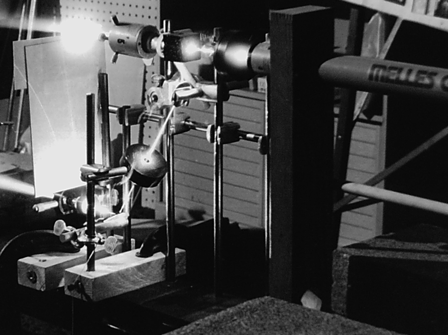
Several vertical rods are cross-linked with horizontals to provide a grid-like attachment in this shot so that a couple of half-wave retardation plates, a polarizing beamsplitting cube and some mirrors can be used to make a two beam diffraction grating. Link. You might never outgrow this device, as it can be used for split beam work!
Five Big Beams were built for Columbia College where I taught the “Lasers, Holograms, and Modern Optics” class from 1985 to 1997. Here they are in action, powered by a mighty, mighty, 800 microWatt Aerotech He-Ne,
and here they are stored until they are needed for the next semester.
Here are some Polaroid SX-70 shots of the Big Beam made by Robert Langston at Morgan Park Academy.
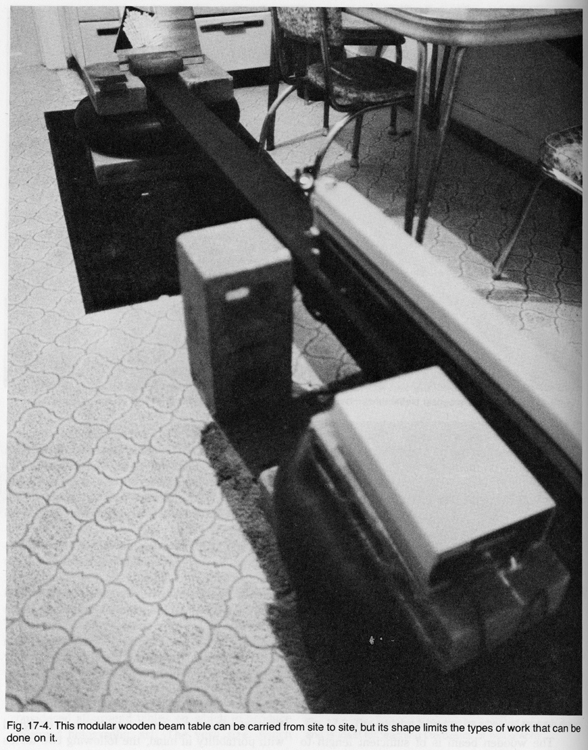
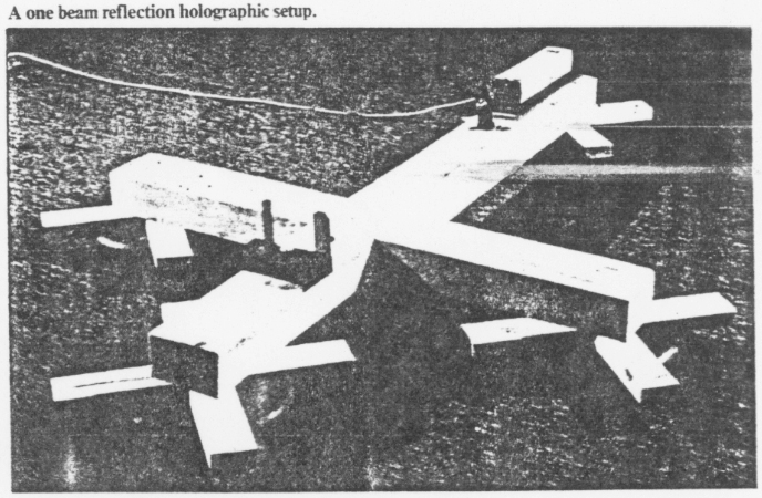
Here is another example of the Big Beam craze that was sweeping the country, from an article by Linda Law appearing in Photomethods of August 1986:
Although not set up for single beam work, here is a Big Beam made at Magnaflux, where I was employed as a Holographic Engineer to do Holographic Non-Destructive Testing. It is a Conductron metal optical rail with a steel plate bolted on at one end, so that a Laser Technologies, Incorporated Holomatic camera is able to look at a piece of laminated honeycomb composite aircraft panel.
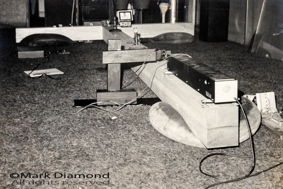
Here is one built by Mark Diamond in Miami in the '80s:
Why not build one of your own?
<back The BIG BEAM next>
<Introduction> <Equipment> <The Big Beam> <Project 1a: In-line "Gabor" type Holograms> < Project 1b: Off-Axis Holograms> < Project 2: Single Beam Transmission Deep Scene Hologram> <Project 3: Division of Amplitude Hologram> <Project 4: Pseudo-Achromat Transfer Hologram> <Project 5: Cylindrical Hologram> <Project 6: Single Beam Reflection Hologram> <Project 7: Image Plane Reflection Hologram> <Bonus Project 1: Diffraction Gratings> <Bonus Project 2: Holoroids>