Plateholder for 2 1/2" (63 mm) square holographic plates on the original BIG BEAM, ca. 1987
I was merrily proceeding along, happily recording Holographic Optical Elements on 15 by 15 centimeter squares of photo-resist and had come to the end of my sensitometric (the never-ending search for the optimal exposure and development time combination) trials at that size so it was time to scale up to the full foot-square (approximately 30 cm). Extrapolating my results from the smaller plates to the 4 times more spread out beam and flux diminished by a quarter yielded an estimated exposure time of one hour for the larger format.
A small plate was shot in the larger spread out set up, being held in the same Pana-Vise, as had been previously used, and there was decent brightness in some areas, but you could see fringes emanating from one edge. Looks like plate movement! So I added braces to the Pana-Vise and hoped for the best. But this didn’t work out either.
So I designed and built a new plateholder out of a piece of aluminum tooling plate. It could handle plates sized from 32 by 42 cm down to 10 by 10 cm thanks to a variety of well-placed plate positioning pegs, with the center of any sized plate located at the absolute center of the holder, allowing a smaller plate to be shot in preparation for exposing a bigger one. Flat head bolts with a taper defined the bottom edge, letting the plate slide backwards to rest against three round head screw heads on the tooling plate, and a third similar bolt, held one side of the holo plate and determined the left edge of the plate’s position. I had previously made one just like this for 63 mm plates and it worked just fine, so why not scale it up?
Plateholder for 2 1/2" (63 mm) square holographic plates on the original BIG BEAM, ca. 1987
This piece of metal was held by a drill press vice on the table. A grating was again exposed for an hour, and still the HOE was plagued with fringes. So it was time to see what the heck was going on, using holographic interferometry!
I had acquired this holographic skill by answering an ad in the Chicago Tribune back in 1984 from a company called Magnaflux, one of the pioneers in non-destructive testing. They had invented the Magnafluxing technique back in the 1920’s, and were looking to branch out into new technologies, holography being one. Out of all the candidates they had interviewed for the job, engineers and physicists included, I was the only one who had not only made holograms but brought one that I had recorded on “The BIG BEAM” to the interview. Check out my resume. So I became their Holographic Engineer!
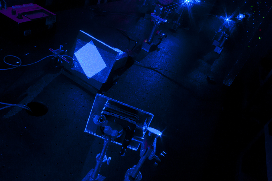
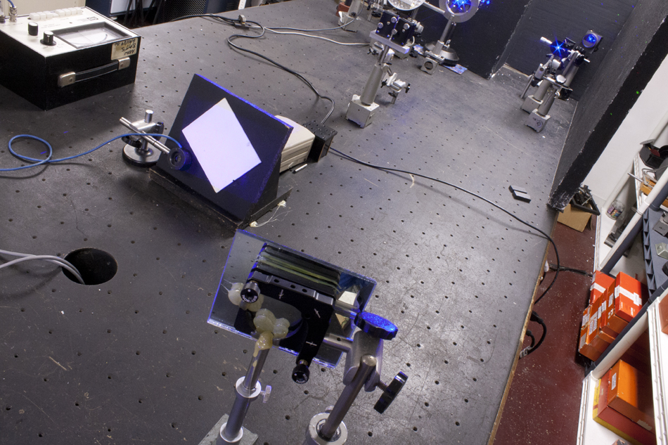
To convert the HOE set up to an NDT one (Non-Destructive Testing) I plopped an Abramson kinematic plateholder into the crotch between the two HOE beams so that it looked square at the big plateholder. A video camera could be placed behind the kinematic plateholder for real-time fringe evaluation if so desired, but this analysis took a double-exposure approach. (Rollover the image for captions.)
The laser, a Melles-Griot BLD-605, emitting a couple of hundred milliWatts at 458 nm, and the beamspreading spatial filter are to the left, out of the picture. A big chunk of aluminum that has been following me around since FermiLab days is to the left of the plateholder to act as a reference surface. Its dimensions don’t allow it to move.
The big plateholder was illuminated by only one of the two beams that were making the grating, in case there was any wandering of the beams. In the tradition of Abramsonian simplicity and stability a mirror was placed in the periphery of the spread beam to reflect light directly to the plateholder as a reference beam. Path lengths needn't be matched, as the BLD-605 passed its coherence test.
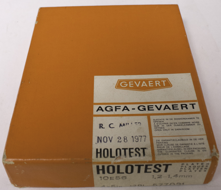
Since the photo-resist exposure time was a full hour, a pair of exposures were shot of the plateholder, 60 minutes apart, on the orders of magnitude more sensitive silver halide based material. To keep that exposure time as short as possible, I opened a fresh (not exactly fresh, a few decades out of date, but never opened) box of Agfa Holotest 10E56 from the Borg-Warner stash.
One of these plates was placed in the kinematic plateholder and a series of test exposures were made, with a development time of in D-19 and fixed with no bleaching to get the minimal useful exposure and to combat noise. There was in image, but it was very noisy, probably because the high speed plates were more like scatter plates at the BLD's deep blue. So I learned something, like to not use these plates for this project. They might work better in the green. Or they might be useful for 2D/3D graphics. Or they might be a waste of time.
So I broke out some boxes that had a motley collection of green sensitive holographic materials circa 1990, like Agfa 8E56 HD with and without AHI (Anti-Halation Intra-emulsion, to reduce scatter) and the equivalent Ilford plates, SP 695T. I had coated their non-emulsion sides with Universal Photonics X-59 Strippable Coating in the '90's when I worked at Lake Forest College! Now they were being shot, over 20 years later!
Did an exposure test and found that all the plates liked to see 200 milliJoules more or less per square centimeter when processed in the PyroChrome system. Shot one exposure, then another an hour later, and found fringes galore.
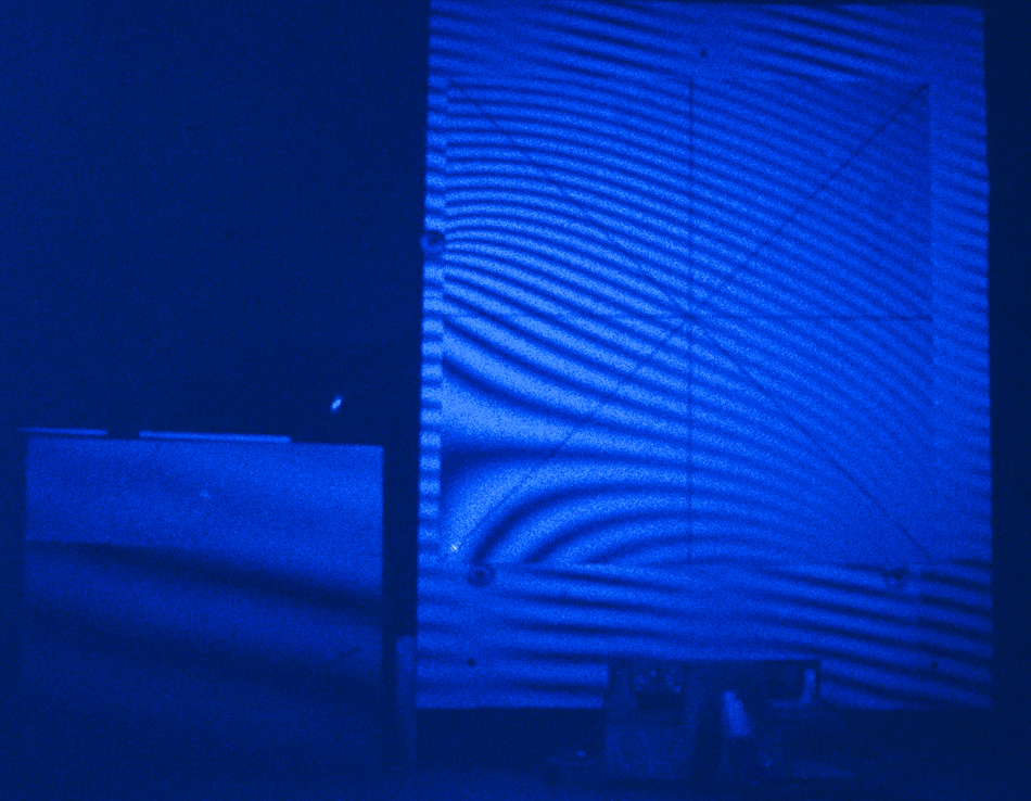
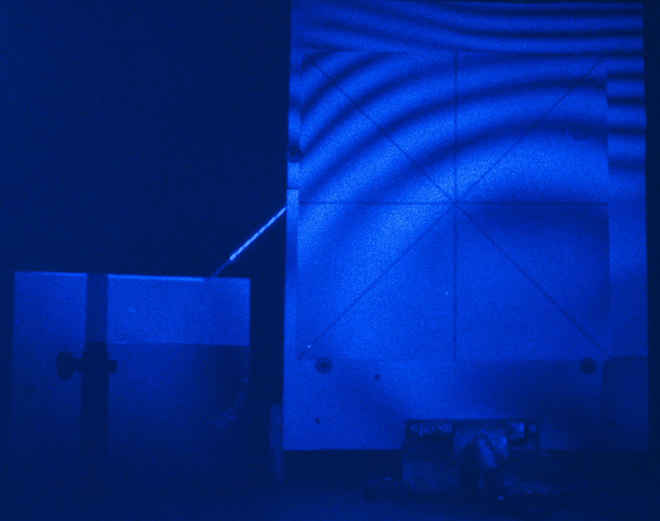
There were different sets of fringes on the big plateholder and the foot square piece of glass painted white that was the alignment target and stand-in for a real plate, meaning that both of them moved and not as a unit. (If the both moved together, the fringes would be continuous over both surfaces.) The beautiful whorl in the lower left corner shows the plate was bowing there, plus some sort of deformation stress by the retaining screw on the upper left side distorted the fringes. The fringes getting more tightly packed at the upper right corner of the plate suggests that it is moving more than the bottom, like it is peeling off the holder. (Closer packed fringes mean that the object has moved that many more wavelengths of light, to put it over-simply. Farther apart fringes mean less movement, and no fringes mean nothing moved.)
But what was the biggest red flag were the fringes on the reference surface. It didn’t move as much as the plate and holder, as there are less fringes, but even so, it weighs 15 kg, so it’s a firm follower of Newton’s First Law. Not believing that it was possible for this mass to have moved during exposure, I blamed the reference mirror, and put a brace on it.
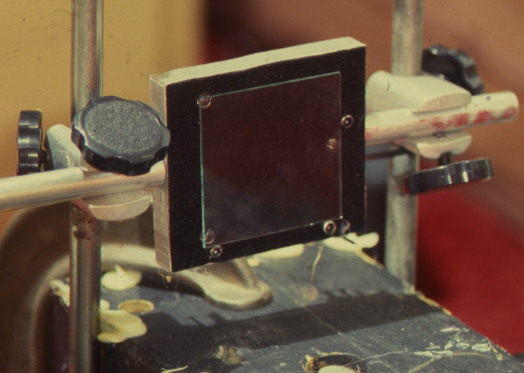
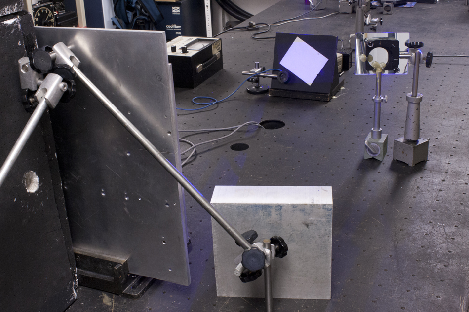
In this reverse angle shot it can be seen how the mirror was braced; a rod was brought into contact with the mirror from below, and hot glued to the glass backing for dampening. Exposures did not resume until everything was at room temperature, needless to say.
In the far upper right corner there is one of pair of spatial filters that were used in the exposing of the grating. (Its twin is in the far corner that is out of the picture, and its light was not used in this experiment for it moved the fringes would get more difficult to analyze.) Its beam was spread large enough to illuminate the plateholder under test with the filet of the beam, and the reference mirror was placed in the almost faded out section of the Gaussian distribution of the laser beam to lower the beam balance ratio, since that light is still coherent with the central spot in spite of being weaker. Controlling the beam balance ratio in this way eliminates the possibility of the beamsplitter and maybe some mirrors and another spatial filter causing spurious fringes.
Lights off and lasers on when rolling over this image, where it can be noted that the orientation of the holo plate is not matched to the orientation of the reference beam, leaving a corner not illuminated. This feature helps in realigning the plate in the holder for reconstruction.
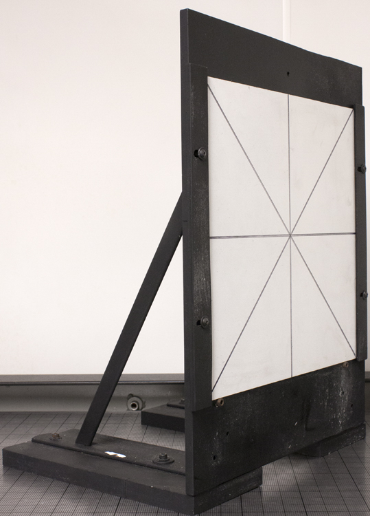
Stepping a bit backward from the previous photograph, this view shows the dual-axis triangulation to stabilize the large cantilever of the tooling plate. Or would they twist it? Note the thickness of the reference surface.
Even so, I was plagued with fringes no matter how I bolstered things; the table was haunted!
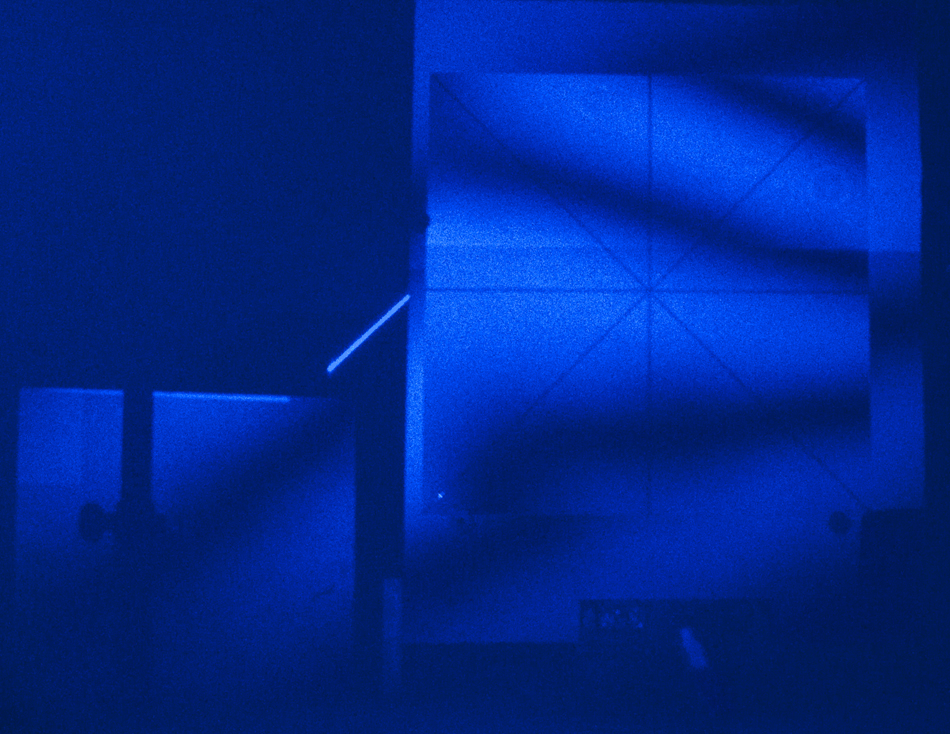
You can see that the plateholder has moved slightly, there are only 3 dark fringes on its whole 40 cm height, and the plate is again moving separately from the holder. What is most troubling is the fringe on the massive reference object.
Finally talked to an expert (Hans Bjelkhagen, of course!) and he said it’s asking quite a lot to find a system that is stable for an hour.
So for how long is the table stable? I made a pair of exposures 5 minutes apart, and the reference surface was fringe-free, but the plateholder and plate were not. The fringes are more numerous at the top showing it moved more, while the bottom moved less. Since the fringes are not parallel lines, the object was deformed and not evenly translated, like the plate got bent backwards by the retaining screw at the top left.
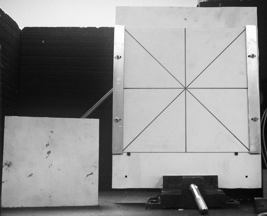
That three point support worked well for the 63 mm squares, but over a 300 mm square the approach didn’t seem to be working. Clamps to trap the plate in the holder were added. Here you can see the modified plateholder resplendent in primer next to the reference surface with the room lights on.
After more interferometric hair pulling the metal plate was attached to massive feet instead of the drill press vise and braced with shelf brackets from the base. That truss-bracing from the top of the plate holder must have been twisting it.
I re-did the interferometry by making exposures 5 minutes, 10 minutes, ... apart, and it turned out that I had about 10 minutes of stability with the new improved plateholder. The problem is no longer the holder but that the table is warping over time. It is endowed with honeycomb rigidity, but it is 4 meters long, supported by 4 legs placed a meter from either end, so it can bow.
When the table bows, with the top concave, distances between points above the table decrease, and when it bows convex, distances between points above the table increase. The change is greater the higher the points are above the table.
Although the honeycomb structure is rigid, at these long exposure times the environmental issues become overwhelming. Even though the optics on the tabletop are enclosed by Styrofoam panels to reduce the effect of wind, the steel skin under the table is not. The room heater turns itself on every 15 – 20 minutes when it senses some change from the set temperature, due to heat loss, even though the room is quite heavily insulated from the elements. Turning it off will only let the room get cooler, letting metal contract. So I implement the fringe stabilizer detector on the top of the plateholder, as that is where the maximum deflection due to concave or convex bowing takes place.
Finally a few weeks after initiating this project I shot a small resist plate on the new plateholder for 10’, the benchmark of stability, quartered it in the dark, and developed 5, 10, 20, 40 seconds, and found my new developing time. Sort of putting the cart in front of the horse, contrary to the conventional wisdom of expose heavy and develop for a few seconds, but it works!
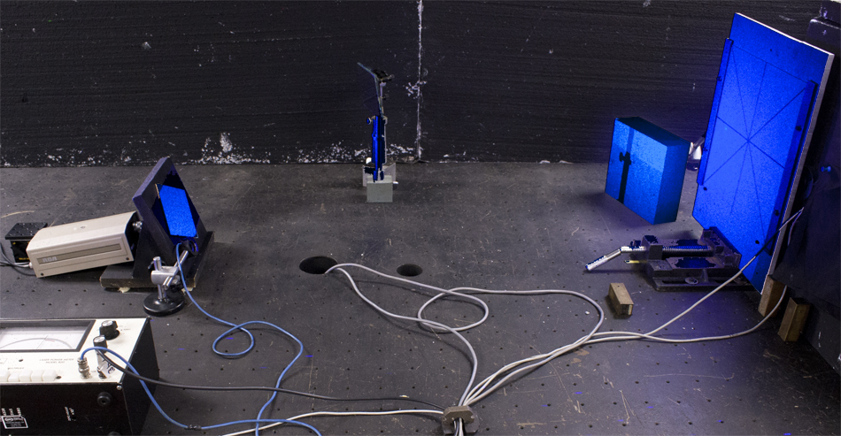
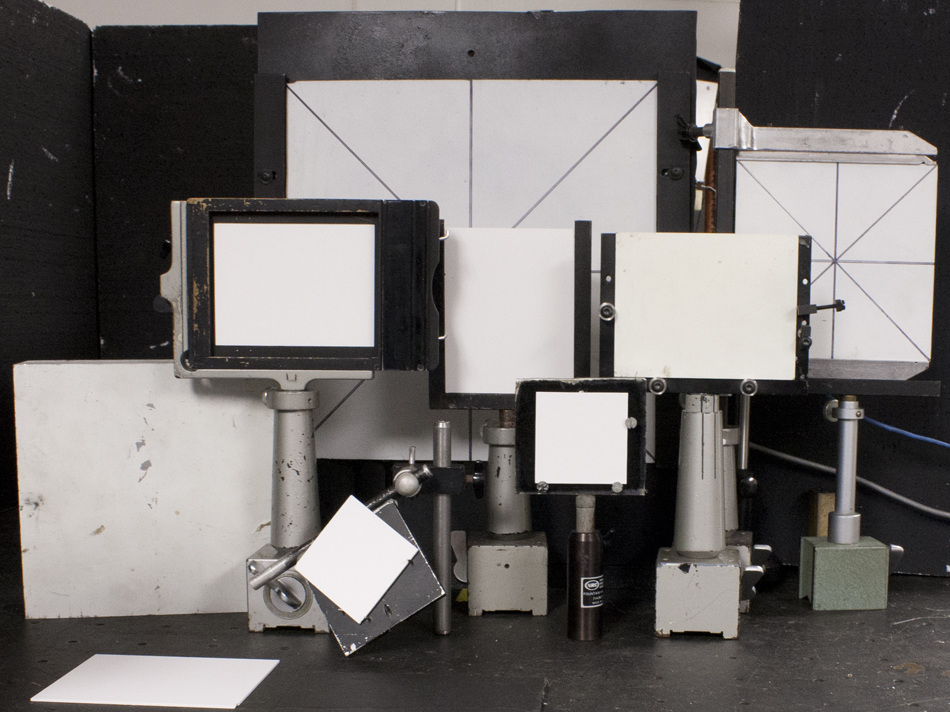
Having so much fun by actually succeeding in resolving a problem with this double exposure technique, I made a farm of all the plateholders on hand and equipped them with former holographic plates painted matte white. Exposures separated by minutes showed that some were very stable while others were maybe best using in pursuing pulsed laser work.
Holographic Interferometry used for Non-Destructive Testing purposes is an important tool for any holographer to be used to examine the set up or equipment. A couple of keys to success are keeping the set up simple, like not using a beamsplitter but a mirror to provide the reference beam, and keeping the exposure time. High speed holography films like the Agfa Holotest 10E series or Kodak SO-253 film or Type 131 plates, are no longer manufactured. But only developing and fixing without bleaching any silver halide holographic material requires only a quarter or less energy than when rehalogenated. (The density need only be in the range of .6 - .8, versus 2.5 or more. The hologram need not be blindingly bright, but useful!