The first holographer that I had heard discuss shooting holograms on the floor was Hans Bjelkhagen in 1981. It was Nils Abramson’s idea, Hans's mentor. They were too poor to afford a vibration isolation table, but Nilsknew that the early Ann Arbor holographers had worked on granite slabs, so why not use the floor to set up holographic recording?
One of my earliest attempts at working on the floor was to record contact copies for Integraf of “The Doctor Is In” hologram. The original hologram was recorded by myself when TJ (Tung Jeong) visited Fermi National Accelerator Lab in 1986, using the word’s largest pulsed ruby laser made for holography, a 25 Joule 4 rod monster built by JK Lasers of Rugby, UK.
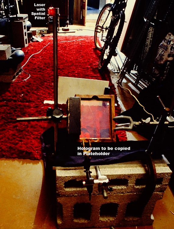
Because of the wavelength shift between recording and copying and replaying, it was deemed necessary to provide as long as a reference beam path as possible to minimize distortions. Although I had been shooting holograms on the “Big Beam”, visible off to the left in the photo below, the longest reference beam path without doubling back with a mirror would only be about a meter and a half. So the set up was moved onto the cement floor to extend the path length.
Copies turned out nice and bright. But since the master and the copy were in intimate contact during exposure, the relative phase between the reference beam, which is the undiffracted zero order of the master hologram, and the object beam, which was the virtual image of the master, would not change as long as they moved together. Same deal with Single Beam Reflection holograms, as long as the holographic plate does not move relative to the object during exposure.
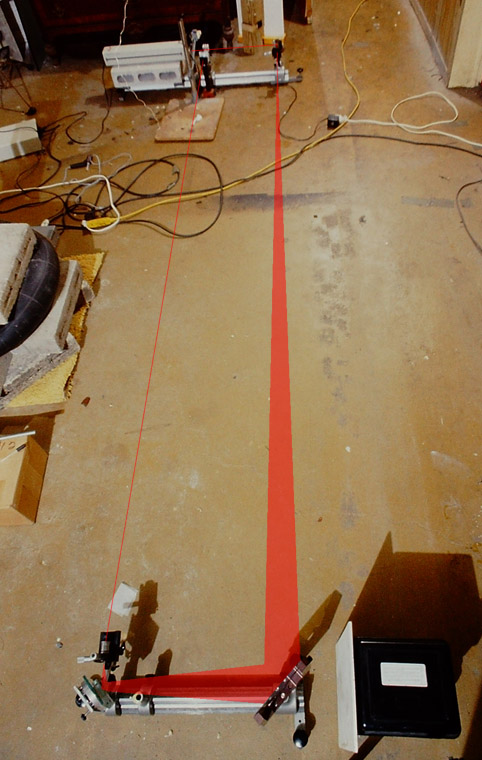
So what about something a bit more demanding, like a split beam Holographic Optical Element? At one end of the holo studio, my trusty 5 mW SP 120 on an Ealing Optical Rail, modified to have 3 point support (instead of the stock 4 points) to prevent wobbling. At the other end of the room, separated from the first optical rail by approximately 3 meters, is another optical rail with the plateholder.
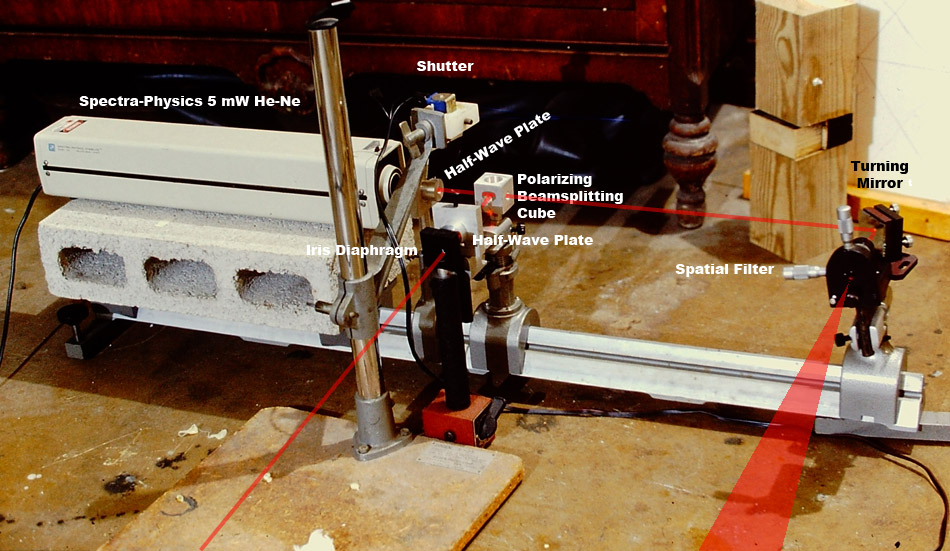
On the rail after the laser are a half-wave plate to rotate the polarization vector before entering the polarizing beamsplitting cube; the polarizing beamsplitting cube, transmitting a beam to a turning mirror which gives the beam a 90° bend into a spatial filter and diverges slowly toward the plateholder’s optical rail at the other end of the room. Tthe beam reflected out the side of the polarizing beamsplitting cube makes a bee line for the platehloder's optical rail, too. A homemade shutter blocks the laser beam and its base, made form my first photographic enlarger, sits on the floor directly
On the other optical rail at the other end of the room, a spatial filter catches the undiverged beam and starts it to spreading strongly, before a turning mirror to send the beam to the plateholder at 45° incidence, where it meets up with the weakly diverging beam from the spatial filter on the other optical rail at the other end of the room, also at 45° incidence.
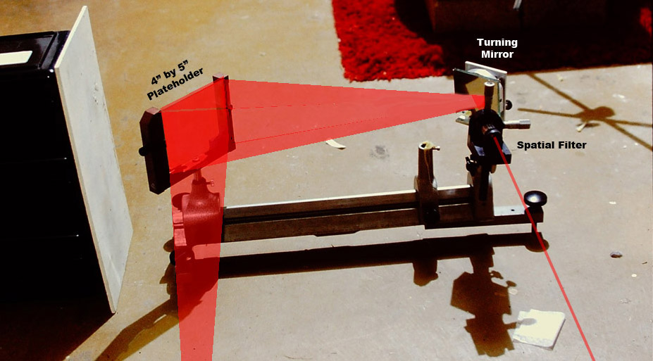
The plateholder is oriented to catch both beams on the same side of the plate to record a transmission HOE; but if it were rotated 90° about its vertical axis the beams would be incident from opposite sides, resulting in a reflection hologram recording. At 633 nm recording λ, the average spatial frequency is in the neighborhood of 2200 line pairs per millimeter, or 448 nm per fringe pair, smaller than ¾ of the wavelength of the recording light, in the ballpark of the tiniest fringe spacing distance of ½ of a λ when the beams come in at 0° incidence from either side of the plate.
The HOE was recorded in the transmission mode as the reflection mode geometry has a fundamental drawback in replay. Ponder it for a second. (The reflected zero order of one beam travels the same path as the diffracted first order of the other beam, so both are seem simultaneously. Tilting the plateholder slightly so that the reflection off the holographic plate doesn’t follow the same path as the interfering beams solves this problem.)
The Agfa 8E75HD plate was processed in CWC2 link for no shrinkage and replaced in the plateholder. Two pairs of real time interference fringes were formed by the first order of one beam interfering with the zero order of the other, although only one set is shown in the image below.
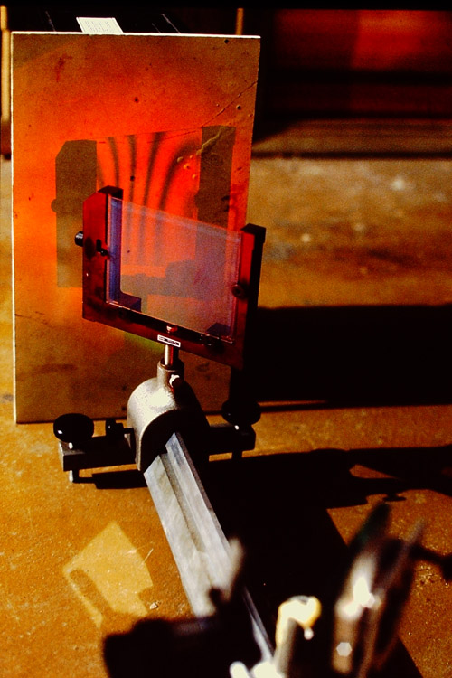
The fringes were quite stable even when the holographer walked on the floor, and even when the washing machine was running in the adjacent room! A lot of mass is the secret!
But the fringes went bananas when the door to the laundry room was opened and a swirling mass of air entered the room! Whether one works on the floor or on a table, enclosing the set up is a must!
So if you have a nice thick basement floor without any cracks, you can practice the fine dark art of holography!