E. Wesly
Studio of E. Wesly & Associates
5318 South Neenah Avenue, Chicago, Illinois, 60638-1230, United States
E-mail: eweslystudio@gmail.com
The use of a contemporary DSLR (Digital Single Lens Reflex) camera to trigger a pulsed (ruby) laser is shown to be an invaluable aid to aligning the laser optics and those in the holographic set up.
Aligning pulsed laser optics has never been easy, as the beam is there and gone in a matter of nanoseconds. The use of a contemporary DSLR (Digital Single Lens Reflex) camera to trigger the laser and record its beam path to align both the laser and the holographic set up is detailed. Unsatisfactory exposures from technical or aesthetic issues can be previewed before development, and the holographic plate erased and reused if necessary. Examples of the working system in use and holograms recorded with its aid are also presented.
The Ruby Laser
Ruby was the first medium to lase, but is not as ubiquitous as other emitters. It is a pulsed only system, and has a low rep rate due to being a 3-level system. This makes tuning one a tedious task as the capacitor bank needs to recharge between each shot, plus the excess heat of the flashlamp needs to be carried away and temperature of the resonator needs to come to equilibrium. Nd:YAG lasers can operate at a 10 HZ rep rate alignment mode, so there is no need to rely on persistence of vision.
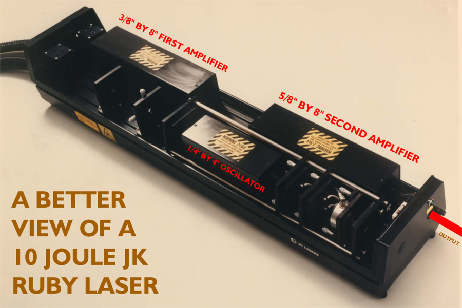
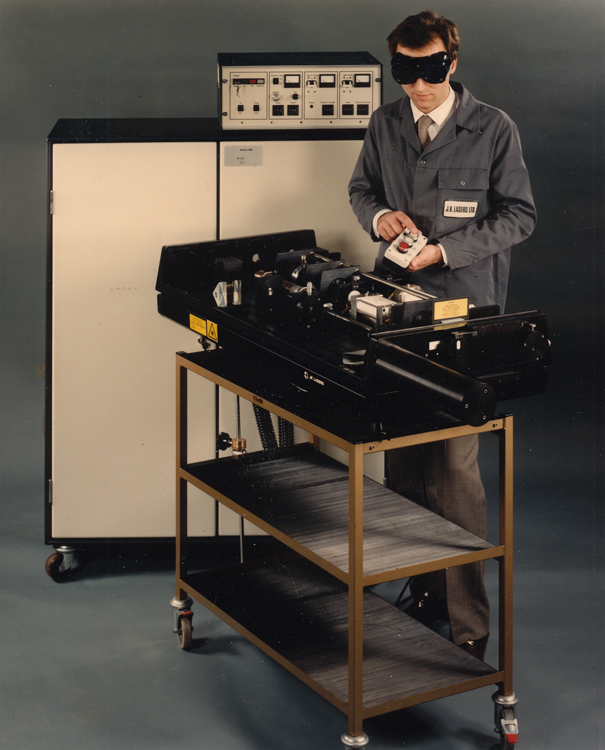
For those not familiar with ruby lasers, here is a primer on the Rolls-Royce of Ruby Lasers, the JK/Lumonics HLS series, from holosphere. Illustrated below is an HLS-4, a 10 Joule unit.
History of JK/Lumonics System NO.5 1051 0
The laser used in these experiments is affectionately known amongst the members of the JK club as the Anait laser, after the original owner, Anait Arutonoff Stephens. I was partially the instigator of her purchase.
“You don’t know who you’re talking to, lady!” “You don’t know who you’re talking to, mister!” That was how the speaker phone conversation ended, the mister on my end being Max Epstein, Ph.D, in his role as President of Holicon, plus the other principals in the firm, Hans Bjelkhagen, Ph.D, and Michel Marhic, Ph.D, were listening in, with the Lady being none other than the above Anait, holographic artist extraordinaire. (She would sign off her letters with AWHOIH, Artist Working Hands On In Holography.)
The shouting match was over the fee that they would charge her for daily rental of the lab. She had been quoted with $500 a day lab rental, but when they all got on the phone, Max was steadfast at a kilobuck a day and would not budge. Even at $500 per diem they would have come out ahead, and would have had a perennial customer.
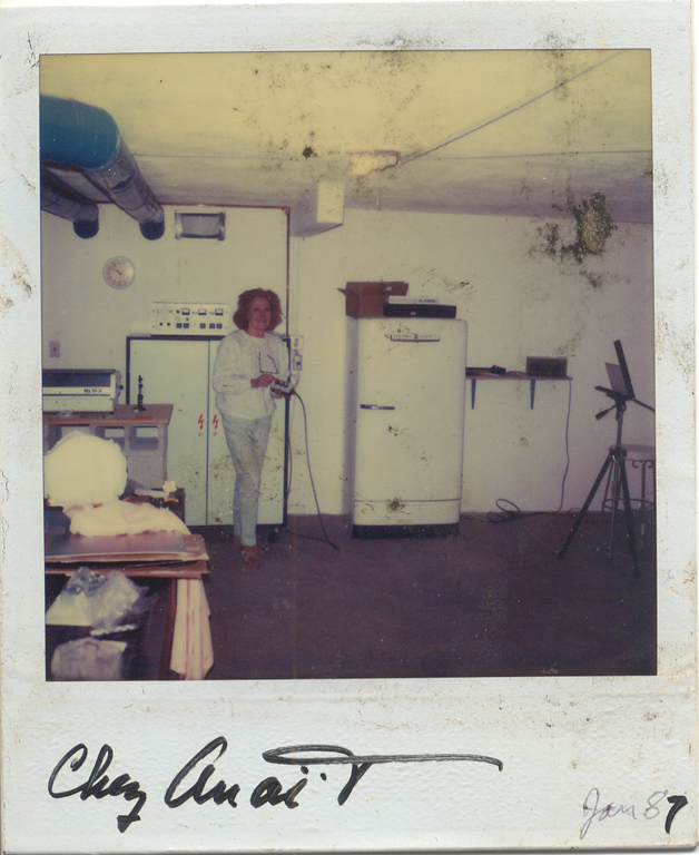
So I called her up the following week to offer my apologies for getting her involved, but she was all right with it, as this was what tipped her over the edge to buy one of her own! At $54,955! Plus she wanted me to come out to Santa Barbara to show her how to make holograms with it. Here she is in her studio.
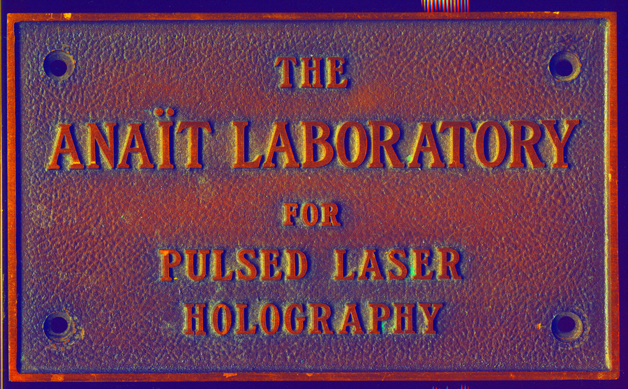
In 1996 Anait donated the laser to the Lake Forest College Holography Workshops, and it was installed in Room B14 in the Johnson Science Center, which was christened “The Anait Laboratory for Pulsed Laser Holography” at the ISDH of 1997.
After lying fallow for almost two decades, it was reinstalled and brought back to life at the Home + Studio of E. Wesly & Sons in Chicago, Illinois, USA in the Tung Jeong Memorial Labseum. The technique introduced in this paper proved vital to its resuscitation.
Camera and Software Requirements
To capture the laser-lit scenes a contemporary DSLR that has the classic manual adjustments of shutter speed, f/stops, and ISO sensitivity with a flash synchronization socket is necessary. Full format or DX sensor size doesn’t matter. A black and white camera, or one with the Bayer filter removed, as in cameras modified for infrared photography, would not be a bad idea as the project is monochromatic and the ruby wavelength is at the borderline of the visible into the infrared spectrum, 694 nanometres.
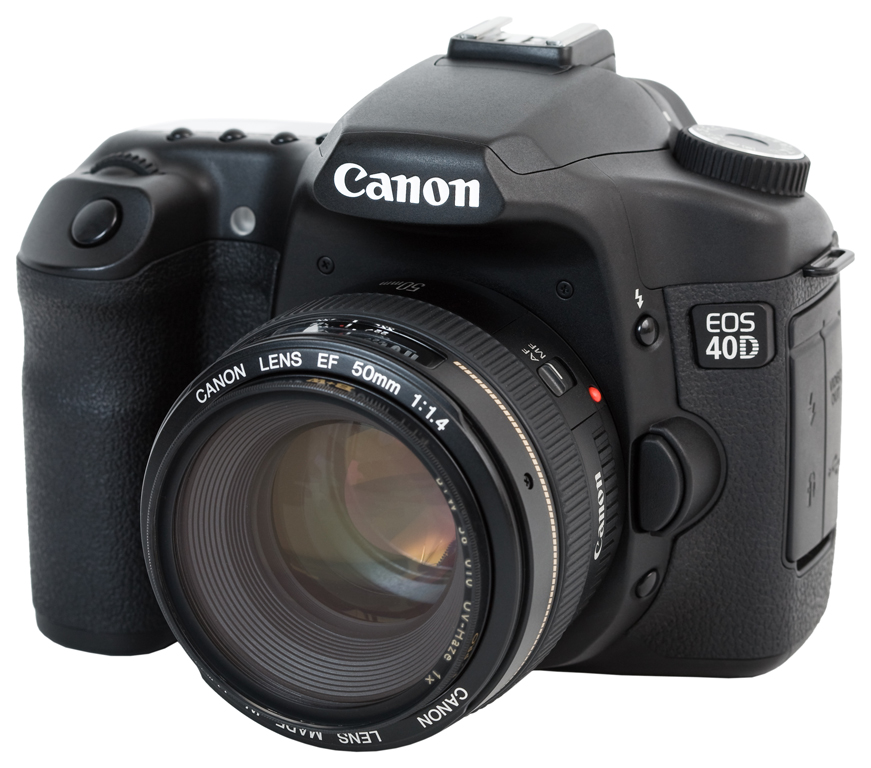
For these experiments a Canon 40D with an APS-C size sensor (22.2 x 14.8 mm)r with an array of 3888 × 2592 (10.1 Megapixels) was used. The 15 to 85 millimeter focal length zoom lens that came with the camera was most useful, to zoom in close on details such as the spatial filter, and wide enough to see the whole illuminated scene.
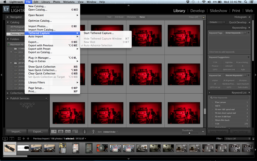
The recommendation for software goes to Adobe Lightroom, but any software that allows tethered capture would suffice. Much of the software that comes with DSLR’s allows that. Using tethered capture to a laptop allows for a comfortable viewing size as compared to the display on the camera, and for zooming in for greater detail viewing, plus organizing and archiving. Progress can be judged from the filmstrip at the bottom of the screen.
An image-editing program such as Adobe Photoshop is a valuable adjunct to the tethered capture software if more zooming in is necessary, and if the camera is calibrated to the software, measurements of brightness and beam balance ratio can be made.
The computing power needed is anything that would allow tethered captures to be performed.
Running the laser as a photographic flash:
The PC contacts in a focal plane shutter equipped camera such as a dSLR closes a switch when the shutter curtain uncovering the sensor reaches the end of its travel (or very near to it). This completes the circuit for an electronic flash to fire.
The External Trigger of the JK responds to a positive pulse of 9 to 15 volts. The flash sync of the camera completes a circuit to the laser using a 9-volt battery to provide the voltage.
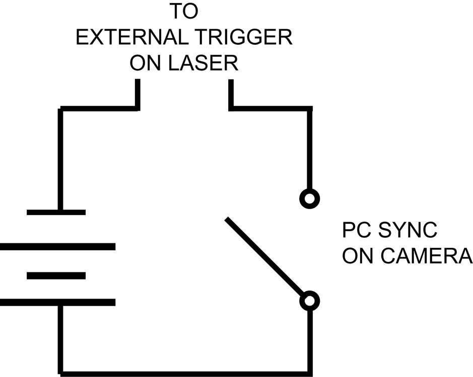
Rather than connect the camera directly to the laser with a PC cord, causing more cable clutter in an already small room, a wireless transmitter gets its order to fire from the hot shoe on the top of the camera, and relays that to its receiver which talks to the box with the 9-volt battery and sends the trigger pulse to the laser.
File Format Forum:
The dSLR’s usually offer a choice of file formats. For aligning the laser, the format of choice is jpg, as they are smaller file sizes so as to not fill up storage media very quickly, as 100’s of pulses may be fired during laser alignment, and there is no need to make high quality prints.
But if quantitative analysis is to be made, like Beam Balance Ratios, the unprocessed raw file converted to TIFF format is preferred, so there are no compression artifacts, which could get ugly when the jpg cosine squared compression deals with laser speckle. Shooting both formats is an option, but fills up memory cards quickly.
Rebuilding the laser
Getting the first light out of the oscillator strictly follows “The Bard of Rugby”, the wordsmith who crafted the Service and Operator’s Manuals. Walking in the output and rear mirrors is still a job best left to alignment lasers and burn paper. But the DSLR pays for itself when it is time to tweak the etalons.
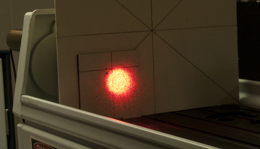
A weak negative lens slightly diverges the oscillator’s beam and an etalon from a Spectra-Physics 125 is placed almost in contact with it. A target card is placed after that, and the camera is pointed at it.
As the bard writes: “With the room darkened, examine the ring structure projected onto the screen when the laser is fired. A series of concentric circles will be seen...” This was a brutal test of persistence of vision in the past, but easily accomplished with the DSLR now.
Photographic Exposure Tests
There will be a need to make some exposure tests with the camera for this operation and all that follow. The shutter speed needs to be one that a photographic flash would sync at, plus a bit longer, as there is about a 25 millisecond delay between the trigger pulse and opening of the Pockels Cell. One fiftieth of a second was the shutter speed used in these experiments and was not varied. Start with the smallest aperture so as to not overexpose the sensor. Start with a high ISO to compensate for the high f/number.
If there is not enough light to see detail, open up the iris. If the scene is overexposed, reduce the ISO number.
A polarizing filter screwed on to the camera’s lens can help attenuate the beam to a comfortable level for the camera sensor in some circumstances.
Once decent contrast is seen in the Fabry-Perot fringes thanks to a workable combination of f/stop and ISO rating, “tilting off” according to the Bard can be carried off with aplomb. After the oscillator is happily tuned, the spatial filter is the next Herculean task down beam. Setting up a white target after the diamond pinhole and firing the laser (free-lasing, not Q-Switched at this stage), looking at the image on the computer, moving the pinhole’s micrometer, firing, observing, makes the chore almost as much fun as doing the same with a CW laser!
Centering the spatially filtered divergent beam through the amplifier rod can be painless if a diffuser is placed at the output of the laser and the camera looks at it from the side opposite the laser. The projection of the oscillator’s light through the rod shows when it is centered, thanks to moving the spatial filter’s lens and pinhole micrometres the same amount. Then the laser is ready to have its amplifier turned on.
This is how an HLS-2 is tuned, the HLS-3 and HLS-4 with three rods would be similar. Or any ruby pulsed laser. Or frequency doubled YAG’s, but some models can be run in a quasi-continuous wave 10 Hz rep rate for alignment that is a distinct advantage over the single pulse ruby.
Holographic Recording Set Up
Once the laser is up and running thanks to the camera, beamspreading lenses can be positioned and centration can be verified without burn paper. Then the range of illumination of the scene can be seen, instead of relying on persistence of vision.
The reference mirror was placed in the periphery of the beam by looking at the scene illuminated by a laser pulse, then locating it the proper distance from the plateholder by matching object and reference path length in the time-honoured string method. This reference mirror is mounted on a ThorLabs Kinematic Mirror Mount, screwed onto a sturdy tripod. The laser is fired again to make sure the mirror is in the beam.
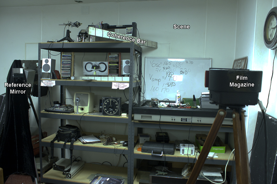
The retroreflector coated piece of angle iron on the top shelf is in this scene to check coherence. The effects of coherence length would not be able to be detected in the photographs, only in the holograms, but that should not be an issue, as the photographic technique would have enabled the holographer to painlessly tune the double etalons as prescribed by the bard.
Its position was also determined with the string so that its centre had the same path length as the reference beam. With a 20 nanosecond Q switched pulse there is a definite beginning and end to the “bolt of light” (6 meters) and you want to have as much as possible of it arrive simultaneously at the film plane.
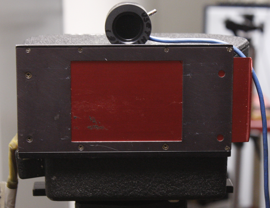
For the reliability and calibration test, exposures were to be made on 70 mm holographic roll film, either Agfa 10E75 or 8E75HD. The film was held in a magazine that holds a 100 foot (30.5 meters) from the type of camera that takes a picture of every student in a school. (Roll over the image to see what's inside.)
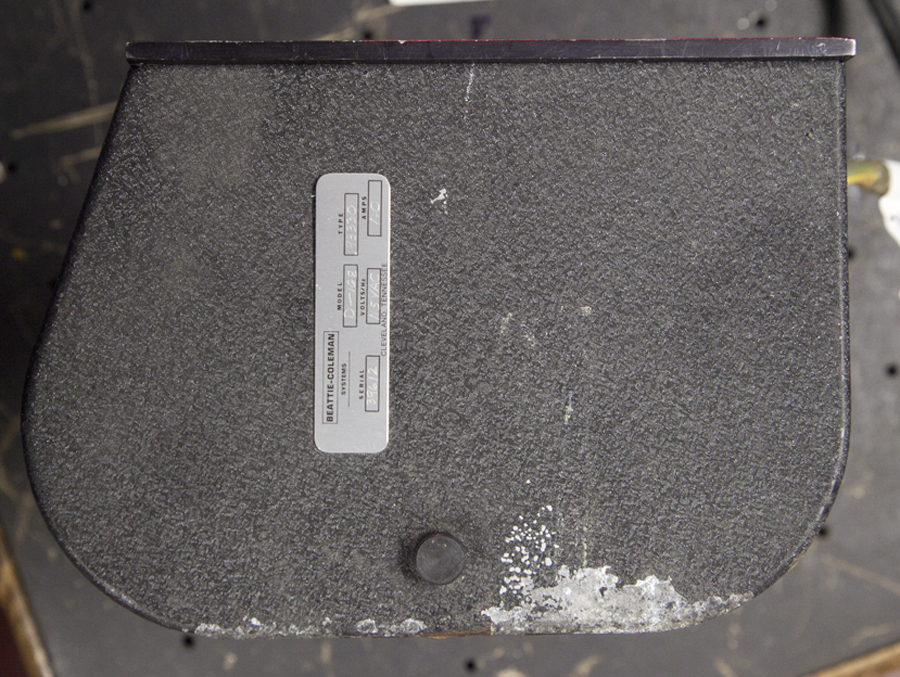
A target card with a gnomon fits snugly into the film aperture. The card has calibrated fiducial marks on it to measure the angle of incidence by measuring the length of the shadow of the gnomon.
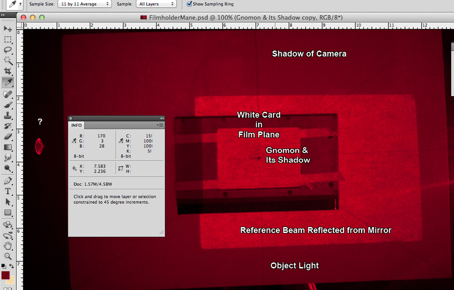
A “mane” is placed around the film magazine, and the camera is positioned to look at the film plane. Then the reference mirror on a tripod can be adjusted to center the reference beam at the desired angle almost as easily as with a CW laser!
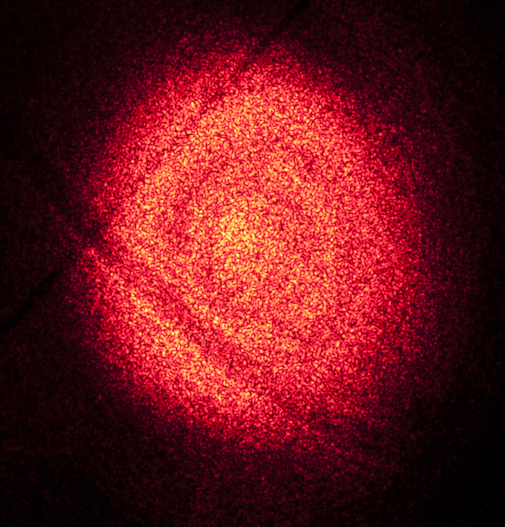
The Beam Balance Ratio can be determined from the above photograph when properly aligned by using the eyedropper tool to measure the object light area and the reference area. The numbers the eyedropper tool displays in the Info Window are sort of like density readings.
In this case, an 11 by 11 pixel Eyedropper sample (to average out speckle effects in the photos, rather than a single pixel source) reads 110 in the object only beam area, 170 in the labelled reference beam area. But the illumination in the reference beam area in the photo is actually the sum of reference and object beams, so the difference between reference and object is 170 – 100 = 60 Eyedropper Units. From calibrating the camera, it was found that 15 Eyedropper Units translated to 1/3 of a photographic stop, so the reference area is 4/3 = 1 1/3 stop brighter than the object beam, for a ratio of about 2.4 to 1, relatively low but still usable.
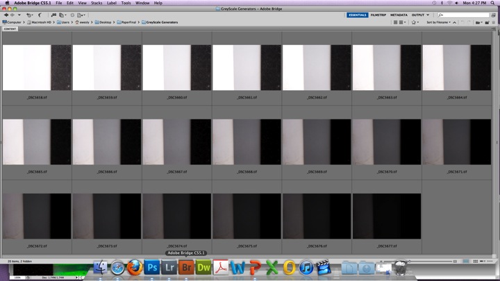
The method for calibrating the camera is detailed here. The gist of it is that characteristic curve of the camera’s sensor is generated by photographing a scene consisting of a white card, an 18% reflectance calibrated grey card and black velvet over a range of exposures from threshold (first exposure where the white card can be distinguished from the grey card) to the saturation exposure where the white, grey and black patches all photograph maximum white. The grey card is sampled with the eyedropper, values recorded, and graphed to form the characteristic curve of the sensor. For the laser work, the sensor should be calibrated monochromatically, either using a red CW laser to light the targets or a Wratten 25A red filter.
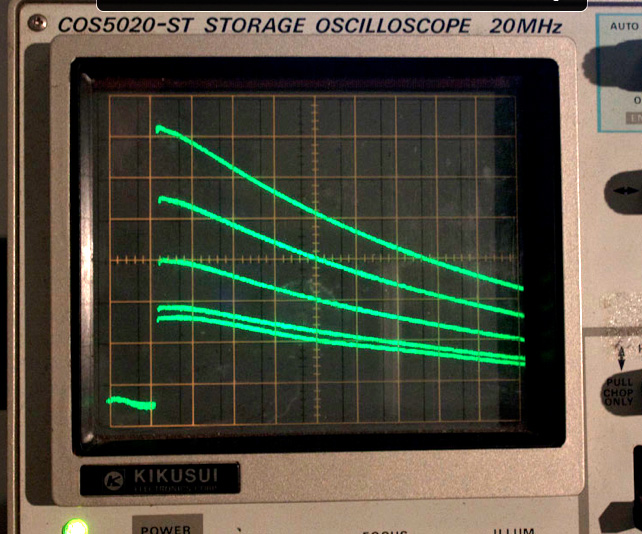
An integrating photo diode rests on top of the film magazine to sample the holographic exposure. A storage oscilloscope displays the energy, and contributes more data to calibrate the set up.
Running the exposure calibration test.
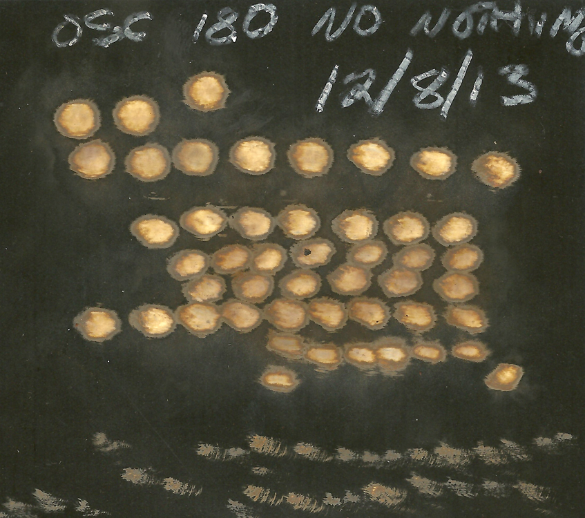
There are digital equivalents to the mechanical shutter release cable, and some of these remote controls have intervalometers built in with shot counters to fire a burst of exposures with a time delay between each one. The DSLR is triggered by one of these devices, which then fires the laser, which sends a signal to the 70 mm Film Magazine to advance. A series of several exposures at a certain amplifier voltage could be shot with 10 seconds between them, then the camera pauses, the voltage is increased to the amplifier, and another set of exposures initiated. Sixty exposures from the 100 foot reel can be processed in a small 70 mm tank, and the effect of increasing energy can be seen through the increasing density on the roll, plus being able to check pulse to pulse consistency.
To record the amplifier voltage in the test hologram the author stepped into the scene and signified the amplifier voltage in Chi-San-Bop, a method of finger counting that goes up to 99 using only the10 digits on a person’s hands. (Thumbs have a value of 5, so 8 would be a thumb plus 3 fingers). Those aren’t gang signs.
Advantages
The benefits of calibrating the photographic camera to the holographic camera are many. If the camera sees sufficient light based on previous calibrations and correlations, then it’s OK to develop the plate.
And if the camera senses more light than usual, (these lasers are capable of playing tricks light that, although they do have a reputation for consistent repeatability), then there is a heads-up to the development department to pull the plate out early.
But if the camera doesn’t sense enough light, or if the expression on a portrait subject is less than flattering to the camera, or if triggering on an event, the trigger was too early or late, the plate could be put aside to be erased and reused.
The camera can be positioned where the subject sits in a portrait set up, to look for stray beams that could be dangerous. Better to burn out pixels than rods and cones. It could also be placed at the viewpoint of the holographic plate to look for the same so there are no extra reference beams.
Hopefully this new tool might arouse some interest in these great old beasts gathering dust in storage and resurrect them.
These types of diagnostic photographs could have been made in the era when the JK lasers were fresh out of the shipping crate, or even all the way back to Maiman’s day, but imagine how much it would have cost to do all this with Polaroid film!
Shout Outs
Would like to give a word of thanks to Bob Hess, Rick Bruck, and Victor Heredia for spending countless unbillable hours with me, trying to troubleshoot the JK when it’s in one of its moods, and a special shout out to Tommy Johnson for all his insights into the electronics of the device.
And of course, our dear old friends who are no longer with us, TJ and Anait, who gave me the gift of ruby light.
The JK Club
The JK club consists of myself, Rick Bruck (who has the Holicon laser), Tommy Johnson, (an Applied Holographics Holo-Printer take out Series 2000 JK) and Harris Kagan at Ohio State University in the USA, (with the Ana Maria Nicholson/Holo-Centre laser). Others may join who might dust off some balky old equipment to get it working, thanks to this new tool that makes pulsed work easier.
The President of the JK club.