Here is a link to the paper itself. It was presented at the Practical Holography session at the SPIE conference in 1990, based on work we had done in 1989 and 1990. The following illustrations might help visualize what was described in the paper
Back then it was hard and expensive to put photographs in the papers, but everyone had their Kodak Carousel tray of slides to show photographs when presenting their papers. I was the audio-visual geek for the group, and following are some images of the lab and the holograms belonging to the paper.
Before Photoshop came around, you could make some interesting text slides by printing out the words and then photographing them with a Kodak product called SO-279. It was a negative color film without the orangey color couplers that give color negative film its distinctive cast. Colorless color couplers were used in this film as It was used for making color positives from color negatives.
But if you photographed line artwork with it, through different colored filters, you could get some interesting color combinations. All the equations and diagrams were photographed with it to make some breath-taking slides, so be prepared for a few examples downstream.
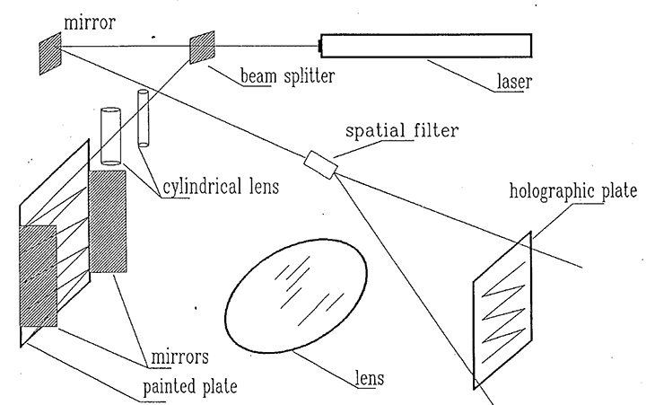
The first mystery in this paper is Dr. Zhimin Qu's coherence measuring hologram set up. Here is a schematic of his ping-pong coherence length hologram set up.
He had a laser beam turned into a laser stripe through a cylindrical lens, and had that stripe of laser light bounce back and forth between two mirrors, leaving its tracks on a piece of white painted metal. The metal plate was imaged by a big lens onto a holographic plate, making an image plane hologram, so that this type of coherence length hologram could be viewed with white light.
Here are some photographs of the set up. In this first one, you can see the metal plate with distance markers on it, with the ping-ponging mirrors flanking the plate.
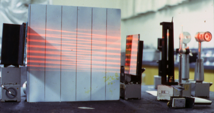
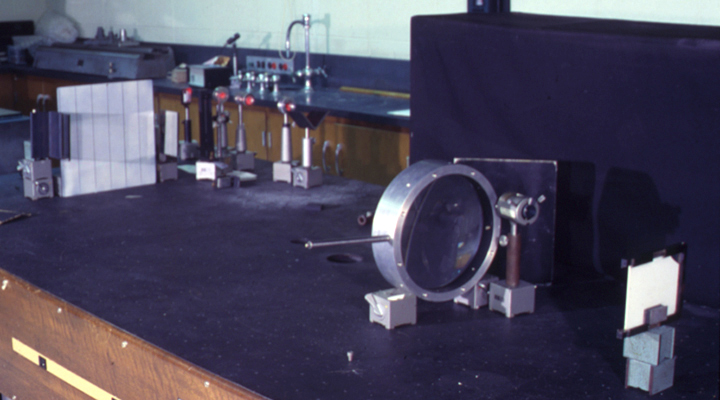
Backing up you can see the big imaging lens and the plateholder. There is a larger object distance than image distance to shrink the size of the metal plate to fit onto a 4 by 5 inch holographic plate.
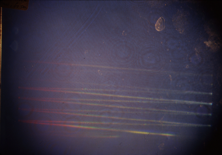
Here is an image of one of these holograms. It is white light viewable since the image is not very deep. The rainbow smears show the coherence coming and going of a Spectra-Physics 125. Because of the folded path, great coherence depth could conceivably be captured without having a deep object.
As you can imagine, this set up needed long exposures! For most of the other smaller lasers, and even bigger ones, the traditional coherence bar was used for the holograms.
I learned this technique from Hans Bjelkhagen when we worked at FermiLab, and here is a link to some coherence work I did with the humongous JK 25 Joule Ruby laser there. I was under the impression that Nils Abramson had invented this technique, but the LFC paper does mention that the coherence bar was first described by a group from Hughes Aircraft’s Holography Group. Here is a link to the Hughes groups paper.
Here is a diagram of the Coherence Length Hologram Set Up. The funny blue color is from the slide film I used as described above.
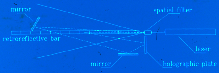
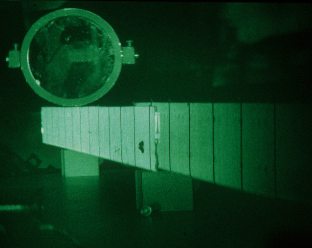
Here is the set up in the flesh. The key to the set up is the coherence length bar, a piece of angle iron covered with Scotchlite brand contact paper. There are tiny glass beads in the coating, which have retroreflective properties, which is why this material is used on street signs. The plateholder is placed close to the beamspreader, as the retroreflectivity of the Scotchlite tries to send the light incident on it back to the light source. But not too perfectly, so that the street signs re-direct a decent amount of light to the driver's eyes and not just his headlights, or in this case to the holographic plate.
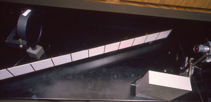
Two reference mirrors are used in this set up, so that the reference beam can be incident at any angle, in this case the typical 45 degrees from normal. Notice one of the mirrors is glued to a big chunk of aluminum.
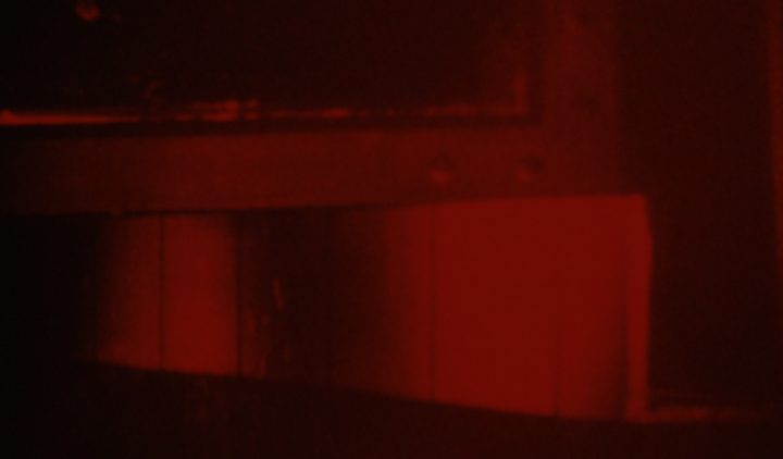
Here is a typical shot from a set up such as this one. This slide was not captioned, so the laser used is unknown, it might be from the Spectra-Physics 124a that is in the picture above, but you can see that the coherence is good for about 2 - 3 decimeters, which is where the markers lie, fades, and comes back. This shot is an example, as its heritage is dubious, but shows you what this type of set up yields.
The set up illustrated below does away with one of the mirrors to minimize instabilities in the system. This makes the reference beam's angle of incidence kind of small, making it hard to look at the hologram without getting blinded, plus if the angle is small enough, there might be some extra images floating around.
Notice that the mirror is labelled R for Reflector, or maybe for Refernece, not M for Mirror. The spread beam illuminates the whole bar, which reflects light back to the holoplate, and big R provides the Reference beam.
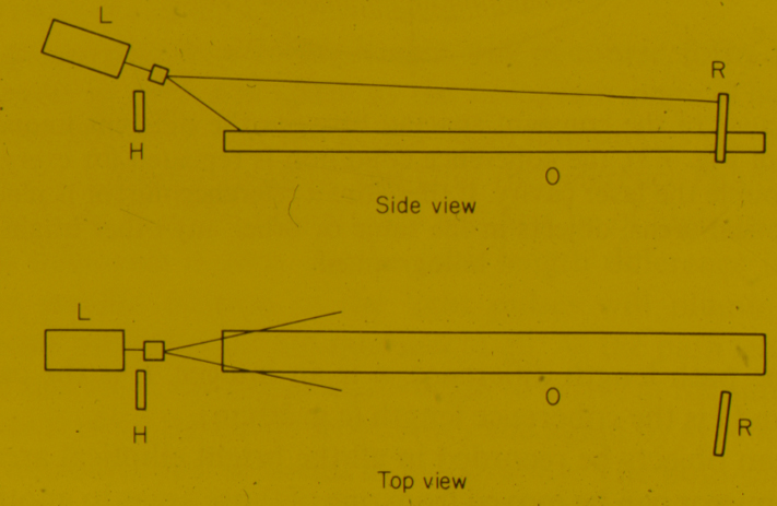
If the holographic plate is placed where R is, then you have the Single Beam Transmission Deep Scene Set Up, which allows you to holograph objects much deeper than the coherence length of the laser, and not a good configuration to measure coherence. See Nils Abramson's "The Making and Evaluation of Holograms" for why this works. See Seven Single Beam Projects on this site for more details on the set up
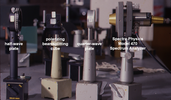
Instead of making holograms, an interesting electro-optical device can analyze the spectrum of laser wavelengths being emitted. The Spectrum Analyzer is a Scanning Fabry Perot Interferometer. (Laser resonators are another example of a Fabry-Perot applcation!)
Inside this device is a cavity formed by a pair of mirrors, and the distance between the mirrors is varied by a piezo-electric cylinder. A laser beam bouncing back and forth between the mirrors can give rise to constructive or destructive interference depending on how well the size of the cavity fits the laser's wavelengths. When constructive interference occurs, some of the light that leaks out of one of the mirrors illuminates a photo-diode, and a spike appears on the oscilloscope trace. If the laser has a family of wavelengths, then many spikes appear on the scope.
Here is how the Spectra-Physics Model 470 Spectrum Analyzer was implemented. For these experiments, especially with the Argon lasers, there was a need to attenuate the beam to avoid killing the photo-diode. So a half-wave plate was introduced, and a polarization beamsplitting cube follows, so that the output of the cube could be varied, starting with a low power to be nice to the photodiode. Then there is a quarter-wave plate after the beamsplitter to provide an optical isolation circuit so that there are no reflections fed back into the laser cavity.
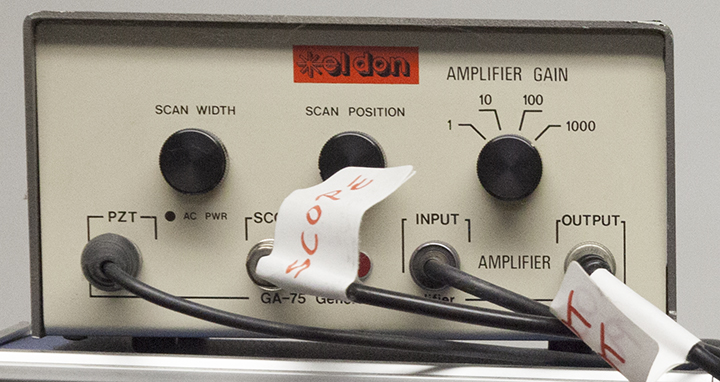
The S-P 470 was driven by an El-Don box! It was hooked up to an oscilloscope, and takes a bit of patience to get a nice sweep, but it is quite wonderful to see the device's depiction of the longitudinal modes of the laser.
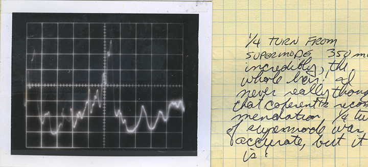
Some of the Cathode Ray Oscilloscope traces were captured on Polaroid film with a scope camera! (Marginal notations in some sweep images are the exposures of the ’scope camera.) I have scanned in the Lab Book pages with the pertinent pictures and paired them with the appropriate coherence length holograms.
When installing an etalon in a Coherent brand Argon laser, the etalon is placed in the cavity and is first tilted so that its faces are at right angles the beam, or parallel to the other mirrors. This tuning is called, "flash", or super-mode, as now the etalon faces create another cavity inside the first one.
Here is the Spectrum Analyzer's depiction of a Coherent CR-2 in this super-mode set up. Notice there are a bunch of spikes, showing more than one frequency resonating.
Here is the coherence length hologram of the laser in this super-mode tune. The beat frequency of the two (or maybe even more) wavelengths causes dropouts in the hologram of the bar.
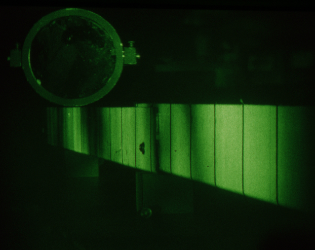
Once flash mode has been established, Coherent then says to turn the vertical tuning knob one-quarter turn to find a good mode. And it works! Here is the scope sweep in the single frequency mode. That garbage on either side of the good spike are those pesky back reflections causing the extra spikes.
And look at how perfectly coherent the whole wave train is, lighting up the entire 2 meters of bar! The blur in the upper right of this hologram is the wall of the lab!
Sometimes a laser is so full of closely packed modes that there is no clearly defined spike. Here is the scope shot of the spectrum of a Liconix Model 4240 50 mW Helium-Cadmium laser. Looks like all grass to me!
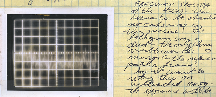
Translation of my lab notes: FREQUENCY SPECTRA of the 4240 - there seems to be absolutely no coherence in this picture! The hologram was a dud -the only thing visible was the mirror in the reference path’s frame. So I want to retry this on unbleached 10E56- the exposure will be...
At first I had tried the set up with the coherence bar going very deep into the scene like with the other lasers; but with lasers like this, of very short coherence, the bar can't extend very deeply into the scene, so I had the bar front and center in front of the plateholder, with just a bit of a tilt, so it's not parallel to the hologram plate.
Here's the entry from the log book: last ditch attempt reconfigured set up. Got 1 full uW at film plane... more info on exposure not relevant to this discussion.
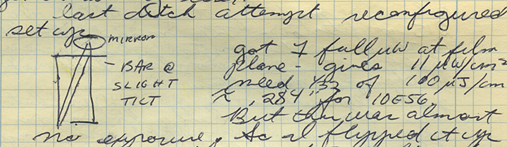
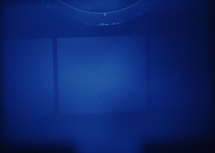
Here is the final hologram. Although one full decimeter is lit up, the path length variation is not that deep, as the bar was almost parallel to the plate as noted. Coherence is probably just a matter of a few centimeters, unfortunately I did not measure the path length differences with a string so I don't have that info logged. Luckily we were only going to use it to make HOE's, but still, there's not much tolerance!
Hope this sheds some light on all the stuff in the paper!