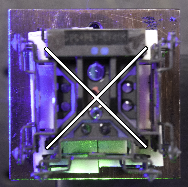
I experimented with a trichroic (for lack of a better word) beamcombiner from a three LCD video projector in an attempt to combine R, G, and B lasers for a forthcoming color hologram shoot. Now I found out that they are called X-Prisms, (here is its patent) but since I like my word and it does describe its function, I will use them interchangeably in this missive. Here is how they put the X in X-Prism:
The one I played with proved to be unusable for this application, similar devices from other projectors or from a 3-chip video camera might be usable, but this was what I had on hand. And I am not so sure where it came from, much less the brand and model of the piece of equipment it came out of.
I cut off the lens mounting flange that was part of its structure and mounted it on a prism table. Putting a flashlight through each of the 4 visible sides of the cube established which ports were red, green, blue, and white. I then labeled them.
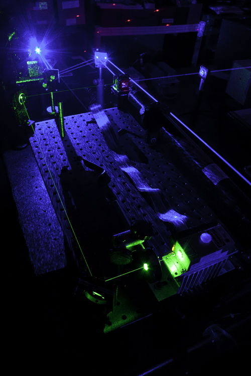
Since the red and green lasers were already mounted on the breadboard, the prism table was situated to take advantage of their orthogonal beam crossing. The red laser was the weakest of the trio, a 20 mW Uniphase 1145P (courtesy of Phil B and Laser Sam), putting out 22 mW, according to my trusty Newport 820, so as to waste as little of its photons as possible, it was the laser that did not get any steering mirrors, but directly impinged onto the trichroic, establishing the beam path height above the table and then the other two would be aligned to it.
The mirrors in the corners of the breadboard allow the slightly higher Coherent Compass 315 beam to be dropped to the level of the He-Ne, and positioned collinear with that beam. An iris near the X-Prism and another at the end of the isolation table, plus a mark on the wall established the beams’ collinearity.
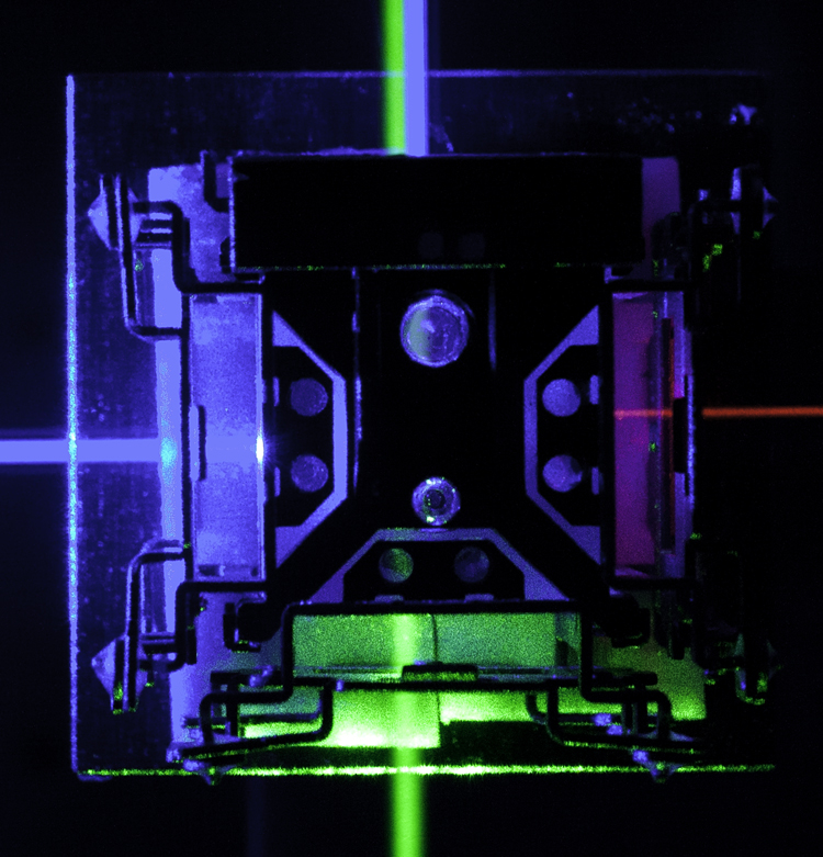
One of the blue beams from the Melles Griot BLD 605 placed near the X-Prism and guided into it by two mirrors, directly opposite the He-Ne. You could see either of the lasers’ beams on the output window of the other, and not really worry about feedback as the frequencies are different than the oscillators.
The beams were made collinear without trying to match their deviations at this point, just to see how good this X-Prism method could be. The first bugaboo is that the green beam, which passes straight through the Trichroic, is polarized orthogonally to the other two, which are reflected by the faces in the middle. One could live with this by placing a half-wave plate after the X-Prism to rotate the polarization to match, but this means opening each shutter consecutively and remembering to change the retardation plate's orientation when necessary, instead of delivering all 3 beams polarized in the same plane simultaneously..
But the worse offense of the X-Prism was what did to the He-Ne red. The beam expanded after coming out of the Trichroic, either due to the spherical aberration of the cube, or one of the faces of the cube has focusing power. This optic came out of a digital video projector and who knows what kind of subtle engineering tricks are built into it. And on top of that, the thin film coating that makes it work acts as some sort of a cavity and turns the He-Ne's Gaussian profile into a doughnut mode!
On the left is the undiverged He-Ne Beam having made a right turn after leaving the laser by way of a mirror; on the right the same beam, making its right turn by way of the X=Prism; diverged and doughnut moded. Both beams have traveled the same distance to the target. Black ring could not be removed by a spatial filter.
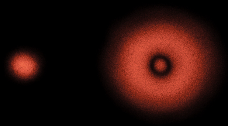
Which makes this optic unsuitable for holography. There may be other takeouts from other brands of projectors, but this one did not pass the test. Oh well!
Research performed January, 2014.