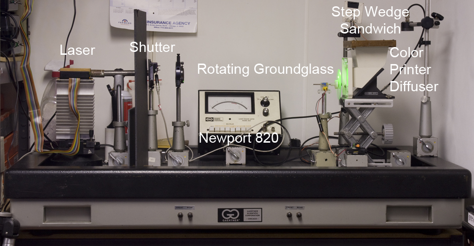
The Sensitometer Apparatus at the Home +Studio consists of a Laser of the appropriate λ of interest, (in this case the 532nm of the frequency doubled Nd:YAG, provided by a Coherent Compass 215, emitting about 15 mW), followed by a Shutter to control the duration of exposition; the undiverged beam is then incident on a Rotating Groundglass disc spun by a Tamiya Mini-Motor at approximately 74 rpm to average out the speckle so there are no interference effects marring the sensitometric step wedges. Care was taken to prevent any stray light from reaching the film by placing cardboard baffles around the equipment along with a piece of pipe for the laser to run through.
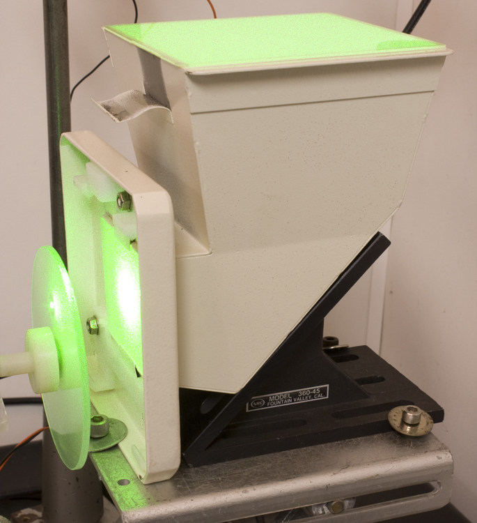
This scanning and scattering beam enters a device from a color photographic printer which was designed to take a white light source and evenly trans-illuminate photographic negatives and positives. Its input and output faces are of some sort of glass or plastic diffuser, and possibly another diffuse reflector of a similar material turns the light 90° inside the device, providing a very even illumination across the surface of the platen, as evidenced by a piece of film placed on the platen and exposed, and measured with a densitometer, with practically no variation from edge to edge.
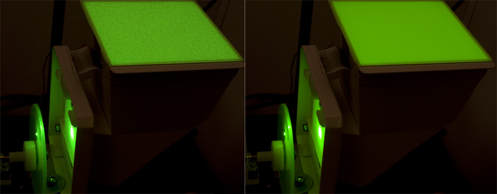
Left, motor off, diffuser speckly; right, motor spinning, speckle averaged out.
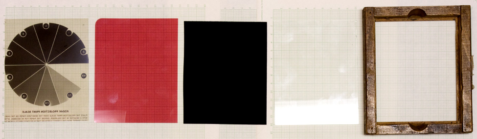
On top of the diffuser plate is placed a Kodak Projection Print Scale, to provide a series of stepped exposures of the light passing through it, with the material to be evaluated placed on top of that, which is capped with a piece of the black flocking material that is used in the inside of telescope tubes to stifle stray light, in this case to minimize back reflections through the emulsion, especially in the case of films without anti-halation backings. A piece of glass follows, to weigh down and flatten the film sandwich, and the border of a Kodak Contact Print Frame aligns all the pieces on the exposing platen. The 4" by 4" squares fit nicely, as well as 4" by 5" sheets.
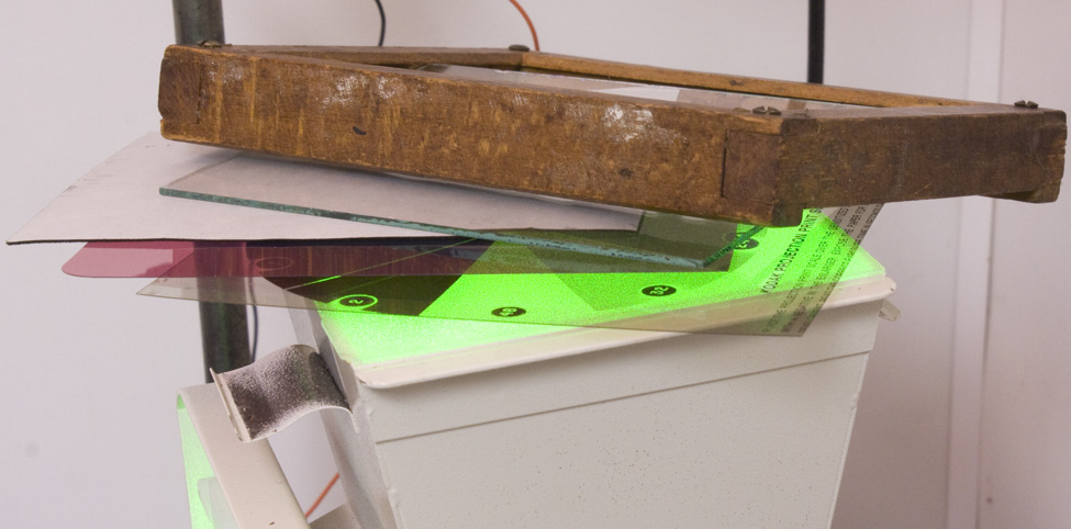
Here are the pieces of the sandwich laid out in a line.
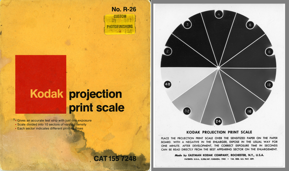
KODAK PROJECTION PRINT SCALE:
This calibrated piece of film was meant to make life simpler for the home darkroom enthusiast by supplying a graduated series of neutral density filters to attenuate the light of a projected photographic negative onto a piece of photographic paper. The neutral densities were selected so that when a 60" exposure is given, the photo paper below each pie slice got the equivalent of that many seconds on the indicator circle. Then the darkroom worker could expose a full sheet at that time for a good print. (Note that when referring to step numbers in the sensitometry spreadsheets, these equivalent seconds are what are called out to identify each wedge.)
For this incarnation, each pie wedge was measured with an X-Rite Model 331 Densitometer, and also measured by a BPW-34 Silicon Detector connected to a Newport Model 820 Power Meter instead of its 1 cm2 detector to measure how much laser light is passing through each wedge to calibrate the exposure dose. The exposure time was chosen so that approximately 100 µJ/cm2 could be obtained under one of the median wedges, like step 8. Here is this calibration, using 40" as the exposure time for the film sitting on top of the device:
Step |
Exposure |
Step |
Exposure |
2 |
23 |
12 |
133 |
3 |
40 |
16 |
208 |
4 |
45 |
24 |
283 |
6 |
83 |
32 |
400 |
8 |
92 |
48 |
600 |
OPERATION:
A sandwich is made of all the above pieces and placed on top of the diffuser under safelight conditions. The motor spinning the ground glass disc is turned on, and the shutter is opened for the appropriate time. After that the exposed film is taken to the darkroom and processed.
All the pieces of film destined for a certain developer were loaded into the racks of Kombi Plan processing tanks so that they were immersed simultaneously. The usual range of development times were 1', 2', 4' and 6', so a piece of film was removed at the 1' mark and placed in the running water rinse, another piece removed at 2', and so on, then they were all reunited in the rack to be fixed, washed, and dried.
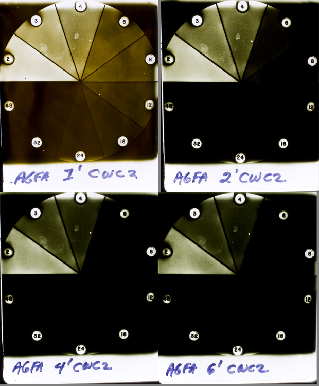
After thorough drying, density measurements were made of each pie segment, 3 attempts being made in each wedge and averaged to give as reliable a reading of density as possible, as there was some schmutz on the Print Scale, as well as fogged spot sites on one film stock evaluated, as can be seen in this family snapshot of development times.
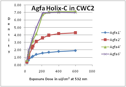
Here is the density data gleaned from the above:
Step |
Exposure |
Agfa 1' |
Agfa 2' |
Agfa 4' |
Agfa 6' |
2 |
23 |
0.25 |
0.38 |
0.63 |
0.75 |
3 |
40 |
0.58 |
0.96 |
1.45 |
1.72 |
4 |
45 |
0.79 |
1.27 |
1.85 |
2.07 |
6 |
83 |
1.04 |
2.26 |
3.08 |
3.38 |
8 |
92 |
1.15 |
2.50 |
3.28 |
3.64 |
12 |
133 |
1.40 |
3.12 |
4.16 |
5.05 |
16 |
208 |
1.57 |
3.60 |
6.72 |
6.95 |
24 |
283 |
1.68 |
3.95 |
7.07 |
7.00 |
32 |
400 |
1.79 |
4.18 |
7.11 |
7.03 |
48 |
600 |
1.90 |
4.28 |
7.15 |
6.99 |
And here is that data in graphical format:
More detailed analysis forthcoming in a link yet to be written.