Almost every holographic tome name-checks the Fresnel zone plate, but I had not ever seen one in the flesh until I finally made my own! It is one of the hardest holographic set ups that I had ever attempted, especially if you want to make perfect ones!
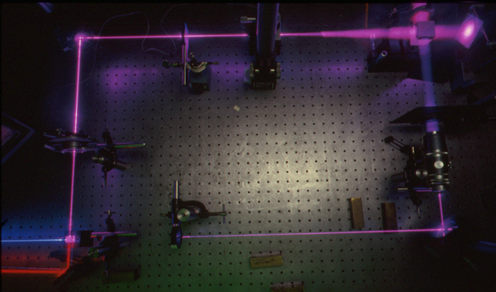
The recording set up is rectangular, based on the Mach-Zehnder interferometer. Depicted below is a zone plate set up made at Lake Forest College with a magnificent magenta laser.
There is no magenta laser, as magenta is a non-spectral color. But a Jodon Model HN-1576 (15 nominal mW in a 76 centimeter cavity) Helium-Neon Laser of 633 nanometers wavelength is combined with a Liconix Model 4240 50 mW Helium Cadmium laser whose lambda is 442 nanometers. These lasers are to the left, outside of the field of view of the picture, but they are parallel to the 4 foot edge of the 4 by 8 foot isolation table.
The level of the He-Cd output sets the height of the beam above the table. A single mirror at the He-Cd's output turns the beam parallel to the table top and long edge. A pair of mirrors brings the He-Ne's beam height to the same level, while injecting its beam into a different face of a Newport Broadband Polarizing Beamsplitting (and/or Beam-Combining, in this case) Cube. Each laser has its own half-wave plate in their paths before the beamsplitter to control the beam balance ratio.
There is a little problem with a beam combiner such as this, as the two different lasers's polarizations are orthogonal to each other while traveling down the same path. In this case, the beam at the bottom of the picture has a horizontally polarized blue beam, as it is transmitted through the cube, while the red beam is vertically polarized, as that beam was reflected off the center cleave of the cube. Half-wave plates are used in each leg after the beamsplitter to ensure that either laser's beams are indeed polarized in the same plane when they get to the plateholder.
No matter what side of the fence you are on in the debate of whether to record holograms with s or p polarization vectors, it is a moot point in this set up, as the beams are for the most part along the normal. The collimated one certainly is, while the divergent one varies from the center out. Anti-halation backing are a must to prevent the dreaded woodgrain in this set up!
The lower beam takes a right turn upward off the Electric Mirror. This is the name given to the Fringe Stabilizer's active mirror by our dear friend, Jesus Lopez, the Mexican Bohemian. Then it goes into a Spectra-Physics Spatial Filter and diffraction-limited Beam Shaping Telescope to become a perfectly collimated 25mm diameter beam, checked by a Shear Plate.
On the other leg, a regular mirror bens the beams at right angles, through an iris, then a Newport Model 900 Spatial filter. The distance of this spatial filter from the plateholder determines the focal length of the Zone Plate, as the other beam is collimated. Otherwise the Zone Plate Maker equation would be invoked:
1/first point source's distance - 1/second point source's distance = 1/focal length
In the upper right corner is a 50 mm Non-Polarizing Beam Combining Cube. The reflection of one path is combined with the transmission of the other path. This actually makes two interference patterns!
Here is a close up of the Beam Combining Cube. It is mounted on a Newport Stage to tilt and rotate it to get the bulls eye of the interference pattern to be centered on the plateholder, which has a white painted alignment plate on it. The design of the plateholder is based on the Kinematic system of Nils Abramson.
The output of the other side of the cube goes through a lens to be magnified to fit comfortably between Fringe Stabilizer's detector. It could also be used to shoot a second zone plate simultaneously with the first! And if one of the Zone Plate patterns had a bright fringe bulls eye, then the other's would be a dark fringe! They are complementary, and show conservation of energy, as where does the energy in a dark fringe go? Into the energy of a complementary bright fringe! All interferometers work this way, generating two complementary patterns! You might have to look hard to find them. (PONDER: Where are they in the classical Michelson?)
The LFC zone plate set up was depicted as I do not have shots of the set up used to make the zone plate included in the pass around package. It was shot not in my home studio, but at the School of the Art Institute of Chicago when the holography lab was in their Columbus Drive building, dating these exposures from circa 1993 or 94. Photons were supplied by a Spectra-Physics Model 127 Helium-Neon laser, and the exposure time was about .1" on 10E75 film developed for 5' in 12 liters of the Pyrochrome chemistry on a 100' reel.
The Beam Combining element in this case was a 60/40 Reflecting/Transmitting plate from Edmunds Scientific. If you look closely at the sample, there is a weak secondary pattern caused by the weak reflection off the second surface of the Beam Combiner. It would be nice to have one that is anti-reflection coated on the non-metallized side.
Fun with Zone Plates!
The real beauty of the Zone Plate is that its orders are not in the x and y directions, but in the z, as you look at the plate. Observe light sources, especially small one like Xmas tree lights, and you will see three (or more, depending on how bright the light is) images behind the film (virtual) and twins to them in front of the film plane (real).
Hit it with a diverging beam, like from a spatial filter, and you will not only see the spots but you can focus them on to pieces of paper! If you look at a white light, you can focus its dispersed image onto your eye socket, much to the delight of someone looking at you.
Sandwich the Zone Plate with other diffraction gratings, and you can make interesting displays of points of light in x and y and z directions!
A Note About the Photographs
On this page, and a few others, the laser beam's paths are made visible by having the camera set on a tripod, in this case a Nikon F loaded with Kodak Ektachrome 50, and holding the shutter open in a completely dark room. Then I ran a piece of Kodak Lens Cleaning Tissue, a lint free somewhat translucent paper, through the beams, so that the laser spots are averaged out with the exposure on the film. Notice I must have forgotten to do the path between the beamsplitter cube and the half-wave plate in longer lower leg. Maybe I will fix it at a later date in PhotoShop. But don't hold your breath waiting!
After tracing the beam paths, I fire my electronic flash to light up the scene, usually underexposing a stop or two to make the table just visible enough without wiping out the beams.