I found this galvo scanner in a box of stuff that had been hanging around in the lab for ages, and would have liked to make a X-Y laser light show scanner with it, but I only had the single scanner. Then it dawned on me that I could pair it up with another piece of laser history that’s been gathering dust, an early generation Spectra-Physics supermarket checkout laser scanner spinning mirror to make a Laser Oscilloscope! The polygon scanner would handle the horizontal sweep, and the galvo scanner the vertical deflection.
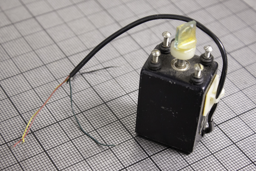
The General Scanning logo is hidden under the cable relief pad, but the Model No. is visible and it is a Z 519, Serial No. 28149. I was not too surprised to find 4 wires, red, yellow, green and black, instead of the two that are there on the moving coil galvanometer scanners that I got from MWK way back in the day. So I figured that there are 2 for the stator, the others for the rotor, but which ones? Plus there were other questions about the device, like what kind of power to feed them, what are its operating limits in regards to angle of deflection and speed, and when approximately was it built?
Google-searching didn’t offer too much, so I turned to the experts at Photon Lexicon and started a thread: http://www.photonlexicon.com/forums/showthread.php/21981-General-Scanning-Galvo
From them I learned that it was an open loop General Scanning galvo. “The four wires are the coil wires allowing you to run the coils series or parallel. Normally you would tie the red to green and yellow to black. Not fast enough for graphics but you could use it with your polygon. Go ahead and connect it to an audio amp output (careful not to overdrive) and have fun!” Courtesy of PhotonBeam, but MixedGas chimed in with “If I remember right its tie black to green and drive red to yellow for series coils.”
Which sparked a splendid discussion about the difference in wiring between series and parallel:
PhotonBeam: “What would be the advantages/differences in wiring the coils series or parallel? Impedence?” and MixedGas came back with: “Makes it hard to exceed the 2.25 amps that demagnetizes the galvo, otherwise more inductance. Brings it to 7.25 ohms reactive where it looks like an 8 Ohm speaker to a amplifier. Sensitivity goes to a more reasonable place for small signals.”
So I went with the series arrangement as I would be driving it from the sub-woofer plug on a crummy little Jensen dual CD player.
MixedGas had another answer, to the historical one: “The Z-519 was what Laser Images used in the Mark IV projector used to do Laserium I. The Mark VI projector used G-124 scanners and was introduced with Laserium II in 1976. These are (I believe) what are called moving iron scanners. The magnet(s) and coils are potted in the housing. It’s a 1960s device modeled off a 1949 servo valve actuator. The design has been continually improved.”
The person who ran the lab that this galvo came from worked at Laserium in that era, so it might be a bit presumptuous of me that my scanner had come from that Laserium projector, but it doesn’t hurt to pretend!
He also urged me to “Go over to the patent server and look at patents by Montagu assigned to General Scanning.” Which I also urge you to do, as this Montagu cat was active in the mechanical television era!
The wires were connected, but the bass speaker output of a cheesy Jensen sound system needed to be amplified, and I had a 386 circuit run off a 9v battery in a project box that I had built for my older son’s first electric guitar experience so he could listen to himself on headphones, before he bought an amp.
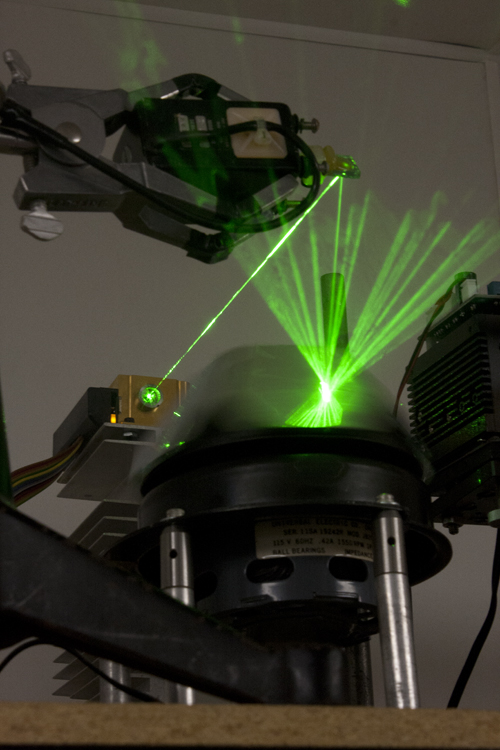
The first iteration of the scanner combination had one of those $90 Chinese RGB lasers impinging on the galvo, and the Spectra-Physics mirror device whirring away.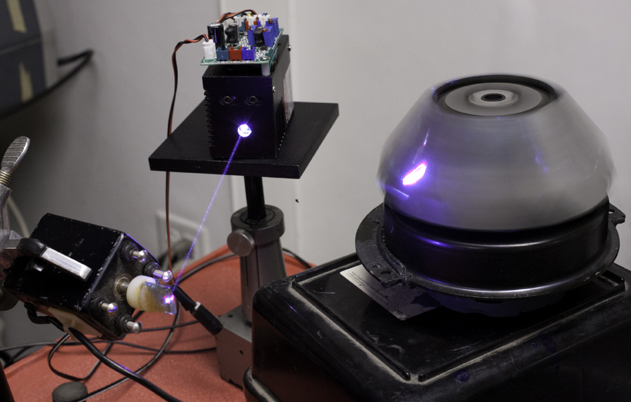
Surprisingly gives the deflection I need!
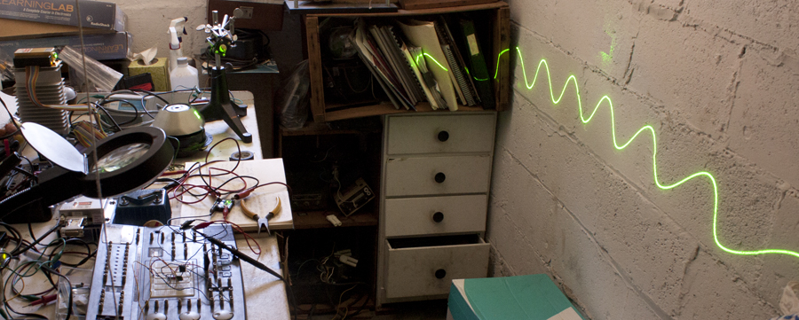
Here is a picture of the scan. The RGB beam has passed through a low frequency diffraction grating to multiply the fun.
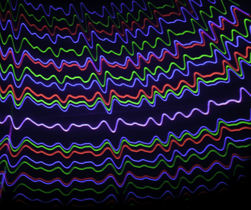
The photo above was made as the mirror scanner was slowing down after it was turned off. When it is running, it is way too fast to make oscilloscope-like sweeps, even if I slow it down with a Variac (variable AC transformer).
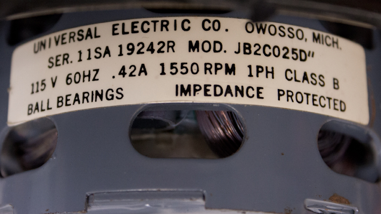
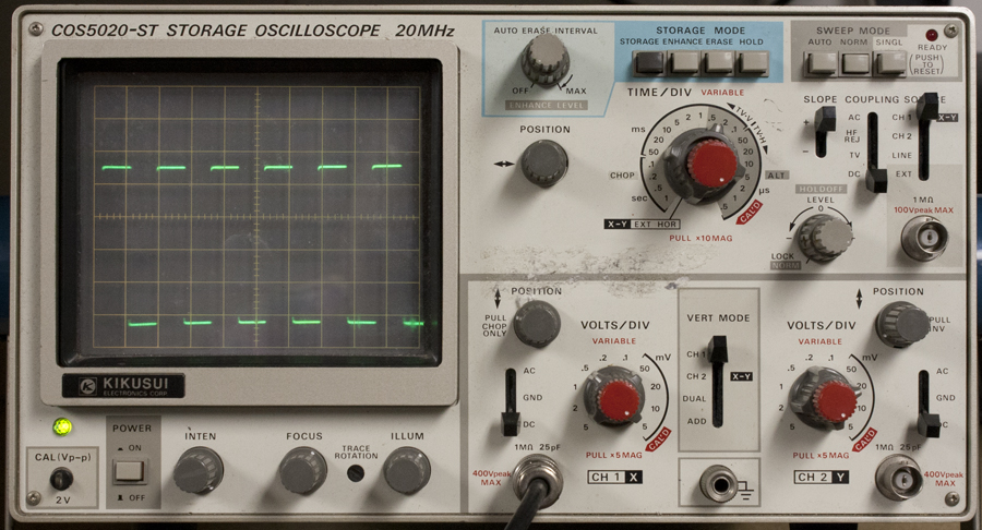
What was needed was a way to slow down the supermarket checkout scanner to match its sweep rate to that of an oscilloscope set up to look at audio frequencies, like 1 millisecond per division, or 10 ms per sweep. Six facets on the scanner add up to 60 ms per rotation, or about 16 rpm, about a factor of 100 times less than the free-running 1550 rpm of the motor! (If I would have done the calculations earlier, I could have used a phonograph turntable that had that speed!)
So my next question I needed help on is “how to slow this motor down to less than a hundred rpm?”
Suggestions included a router speed control, or a light wall rheostat, or some kind of SCR circuit to have speed control with that 60 Hz AC motor. Having tried the Variac, which delivered low voltages but that was not enough to force the motor to spin, and being dimly aware that toy train locomotives could be made to crawl by using Pulse Width Modulated DC, I decided to build a circuit to pulse width modulate the AC going to the scanner motor. Doing some research on-line I found that it was discussed, but no details except that it required kHz of modulation. So I built a circuit using a 558 Quad Timer as a Fully Adjustable Pulse Generator following The Forrest Mims Engineer’s Notebook (p. 119) on a Radio Shack Electronics Learning Lab to switch a solid-state relay. Surprisingly it worked!
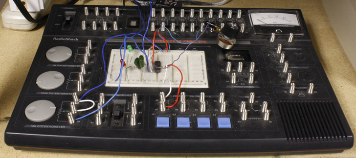
The circuit evolved into using .47 microFarad capacitors and 100 kOhm variable potentiometers to vary the pulse width and separation, and the scanner spun at an appropriate rate with a duty cycle of .5 ms on and the same time off, giving a period of 1 ms, or a frequency of 1 kHz.
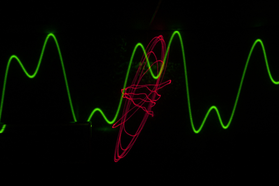
Here is the demo done in the Home + Studio’s electronics lab, with a Lionel toy train transformer supplying the sine wave to the vintage galvo scanner. The scanner could take all of the 12 Volts the transformer could deliver!
The motor does get hot, but I don’t run it that long, just enough for demos. I will include a fan when I get around to building an enclosure for it, but right now the spindly little legs allow enough air flow for demos.
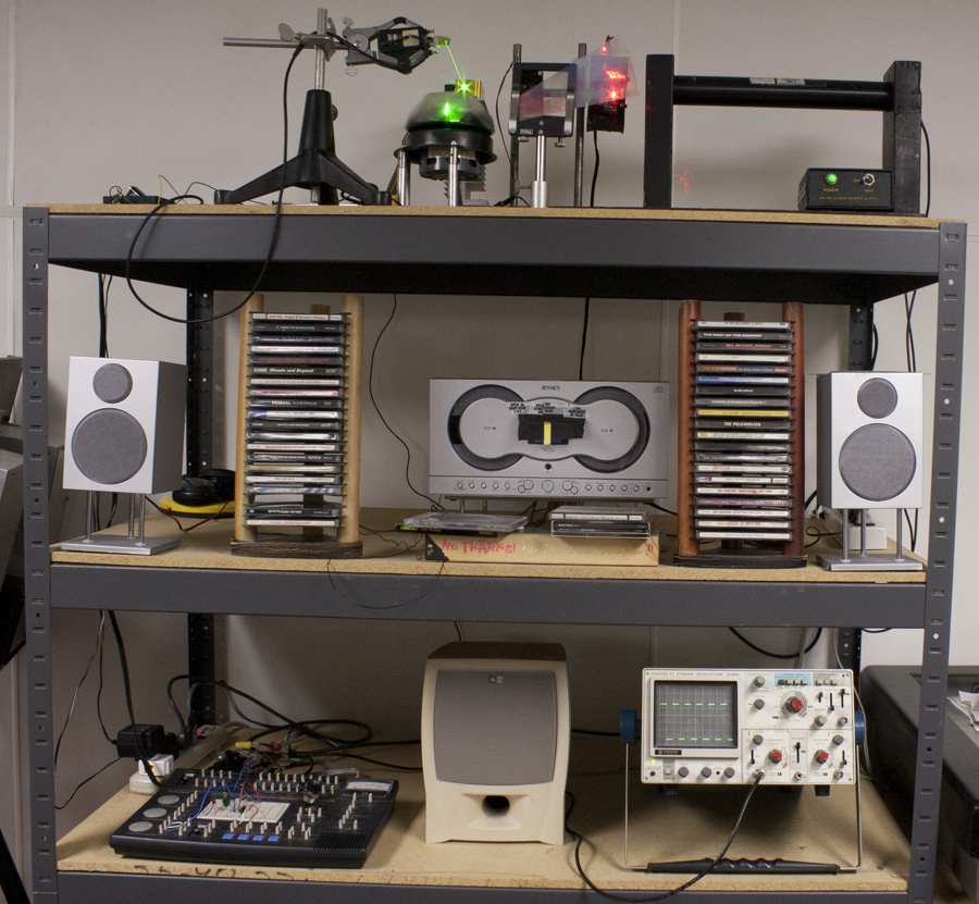
This laser scanner adds to the MWK two axis scanner take out from a Video Disc player I’ve had for decades! The laser beams are projected on to the wall oposite to the Lab Entertainment Center, so it's like being inside an oscilloscope!
After a hard day holographing, it’s a pleasure to work on junk like this!
A big shout out to all the help I've received from the crewe at Photon Lexicon!
Here's the Lab Entertainment System: