The INTERROGATION SET UP:
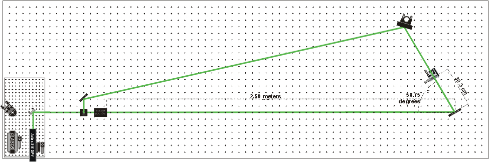
An interrogation station was assembled to evaluate the diffraction efficiency of some Holographic Optical Elements that I had recorded for a client. The HOE was the recording of two interfering beams, one positioned 2.6 meters away from the plateholder, incident upon it at about 57 degrees, the other aimed straight at the plateholder along its normal, 30 cm away.
It was decided to flush out the real image of the pinhole of the short beam path so that it could be focused on a power meter's detector. Since this pinhole was only about 30 cm from the film plane during recording, a detector could be easily positioned on the optical breadboard in the focus, and the intensity of the output from the HOE could be observed on the meter head while manipulating the film to find the brightest image.
Because there are inevitably some inhomogeneities in the densities of a hologram either due to woodgrain or not well-filtered laser beam artifacts, it was decided to use a larger than undiverged laser beam to sample the holograms that were shot on full 4" by 5" sheets to average out the blemishes.
The light source for the replay system was a Coherent Compass 315M whose output was dialed down to 5 mW, not for coherence's sake but because more light was causing the HOE's to printout while being interrogated. The polarization vector of the laser was aligned to be as it was during recording with a half-wave plate added to the optical rail.
To conjure up the true undistorted real image of the short beam path's point source, the illuminating replay should be converging to the same spot behind the HOE that the long beam path wavefront had come from, 2.6 meters away. A Spectra-Physics Model ___ beam-shaping telescope was called into play to provide just such a converging beam, as the optic can not only collimate a laser beam, but it can also focus the beam to a diffraction limited spot far away from its objective. A target was placed at the appropriate distance from the HOE and the telescope focused onto it.
The film was held by its edges during replay, not sandwiched between glass, to eliminate the effects of 4 more optical surfaces. This filmholder was adapted from a traditional "Graflex" film holder for 4" by 5" view cameras. The central area of the filmholder was cut out while the edges of the film were held by a pair of grooves at the perimeter of the film sheet. Flatness was not perfect, but satisfactory.
This Riteway Regal filmholder was screwed onto a Gaertner Plateholder mounting frame. (This device had originally held a Graflex style glass plate holder, so it was an easy substitution.) This right angle mount was mounted on a Newport Rotating Stage, so that angles of incidence could be measured. The Rotating Stage was screwed onto a Newport 430 Translating Stage, which was attached to a Melles Griot Damped Rod with a geared mount, so the beam can access any part of the HOE.
Calibrating the set up:
The Newport 820 Power Meter's detector was placed near the focus of the beam, over
a couple of meters away from the film holder, so that the converging rays under-filled
the detector. A sample of the clear film base that had been cleared in laundry
bleach of emulsion was placed in the film holder, which was rotated to the
reference angle, and the intensity of the beam passing through it was
measured. This was deemed the quantity of light that was then reaching the
holographic emulsion through the film base. An iris diaphragm placed after the
beam shaping telescope could fine tune the intensity of the light at the far
focus to a number that ends in 5 or 0, and was useful to stop down the beam to
a manageable size when interrogating the quadrants of a test strip.
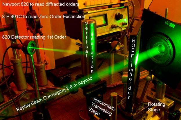
On the operating table another photo detector, from a Spectra-Physics 401C, intercepted the converging rays and was cross-calibrated to the Newport 820. This detector was used to measure the extinction of the zero order beam passing through the HOE. The Newport 820's detector was removed from the remote outpost and was then used to measure the 1st order output, 30 cm away from the HOE.
Interrogation Procedure:
The hologram of interest was loaded into the filmholder, which was in its home position,
meaning that the replay beam was incident at the same angle as the long beam
path when the hologram was recorded. This angle was verified by a gnomon
method, matching the shadow cast by nail on a card in the recording set up and
to that in the replay set up.
The Zero Order Extinction (ZOE) at this replay angle was measured by the S-P 401C, duly noted, and the Newport's detector was positioned in the focus of the short beam path's real image, and also recorded.
Then the filmholder was rotated, and the ZOE on the 401C was observed, looking for any decrease in intensity and following it until it bottomed out, as that is usually when the diffracted order peaks. The Newport detector was then repositioned in the new real image position.
If there was a faithful recording of the fringes, no distortions due to shrinkage of the emulsion, then the Best Zero Order Extinction (BZOE) would occur at the original reference angle. But this was usually not the case; most of the time, and especially for the most efficient samples, this position was about 3 to 10 degrees off from the original recording geometry! And then there were two very distinct astigmatic foci. Which could be a very serious issue for making transfer holograms.
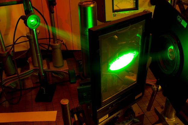
As can be seen here, when the HOE is interrogated at the recording angle with the conjugate beam, the real image of the short path is free of aberrations, as below.
Higher efficiencies could be attained by tilting to a larger angle off the normal, however the output beam became very astigmatic.
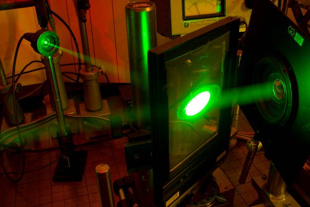
Here is the vertical focus, if you reference the HOE lit from the top, or tangential in optics speak. Notice the meter reading on the S-P 401C whose off-screen detector is looking at the zero order is practically zero. The quantity of light on the detector depicted but whose readout is out of the scene is 1/2 of the light incident on the HOE.
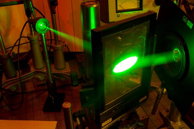
Here is the other focus, the sagittal, and it is about a centimeter further back. The amount of light on the detector is the same as the other focus, as long as the sensor is under-filled.
So if there is almost no straight through beam, where is the rest of the light going? An overhead view of this interrogation set up shows where.
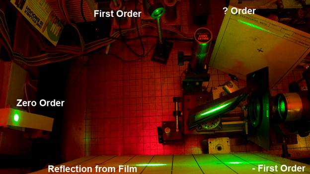
A piece of paper covers the detector of the S-P 401C Meter to make the Zero Order beam visible. Going clockwise from there in the photo, the First Order beam is on the Newport Model 820 Detector. Then there is a very astigmatic beam on a piece of FermiLab Engineering Note Graph Paper; some sort of a second order. (The math needs to be done on this beam along with a few others.)
Below the HOE in the picture, emerging from it in a Bragg Diffracted way, as the interrogating beam is incident on the plastic film base, not on the emulsion side, so it is not impinging on a surface relief, is labeled the negative First Order. It is 180° opposite the strong +1 order. And then there is the specular reflection from the film base, which is practically nothing when the HOE is replayed at its recording angle, but its Fresnel reflectivity creeps up at the angle of incidence is increased.
To visualize all the beams diffracted, transmitted and reflected from the HOE, another interrogation station was invented using the ray-tracing principle. A pair of Optical Protractors (protractors with 0° and not 90° denoting the normal) were designed in CorelDraw, and printed out, and nestled on either side of an HOE in the filmholder. The round beam of another 532 nm emitter passes through a glass rod acting as a cylindrical lens to generate a stripe of light on the protractors, and all the beams emanating from the HOE can be seen.
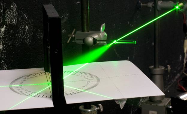
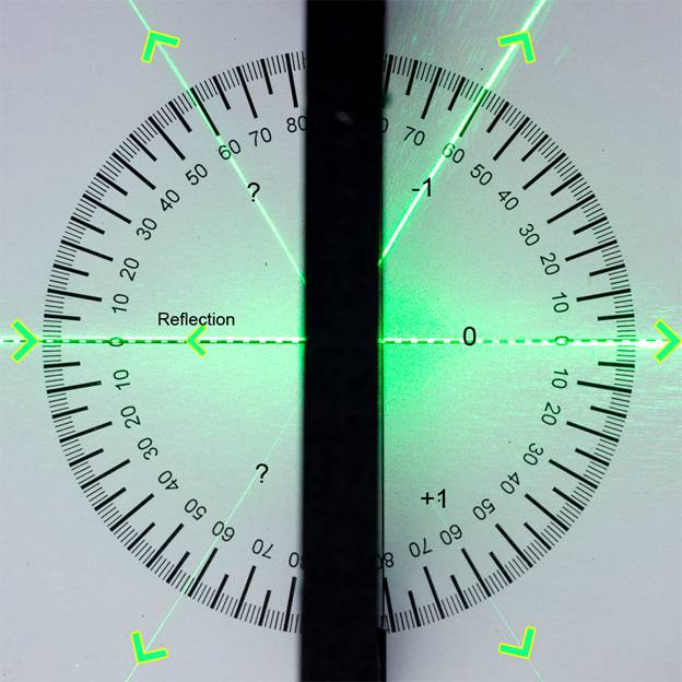
In this next image looking directly down on the station, the line of light is entering from the left, incident on the HOE along the normal, so its reflection is doubled up on top of it and not discernible. The strong first order diffraction of the virtual image of the long leg point source is readily apparent, labeled -1, as this would be a ray coming from the virtual image of the far away other interfering beam. Some weaker diffracted orders are evident, and they seem to mirror that strong one along the normal and the film plane, suggesting that they are the products of spurious gratings that were formed by internal reflections of the two interfering beams in the holographic emulsion.
The filmholder is on a rotating stage, so the HOE could be interrogated at any angle of incidence.
The most efficient holograms recorded on the table set up and interrogated in this set up put a healthy 44% of the incident replay beam into the first order, not too shabby for some 20+ year old silver halide film! The other 56% went into the other orders, with a bit being lost to the scatter of the grains in the film.