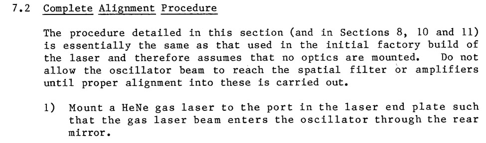
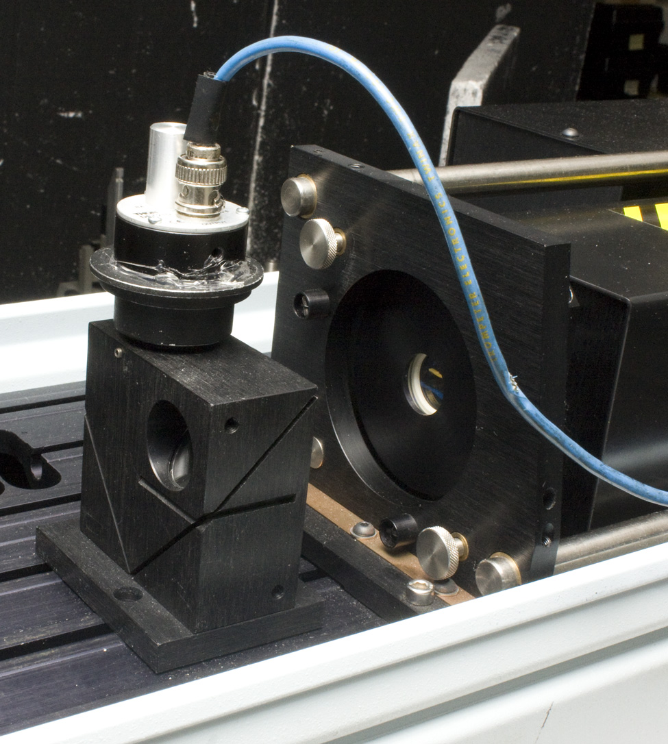
Here is the JK official issue He-Ne laser mount, which came with the Anait laser, with a randomly polarized Hughes 5 mW laser in it. The laser mount had been oriented so that vertical adjusters were at the top, which meant that the springs surrounding the laser had to push the laser against the adjusting screws, against gravity, which caused some drifting. This mount was then rolled so that the vertical adjustments were on the bottom of the mount, so that the laser rested on the screws naturally by gravity. The springs only had to push the laser against the horizontal adjuster. There was a thought that the adjusting screws should both be at the bottom, at 45 degrees from the vertical, but then the adjustments would not be in the same plane as the adjustments of the oscillator's mounts.
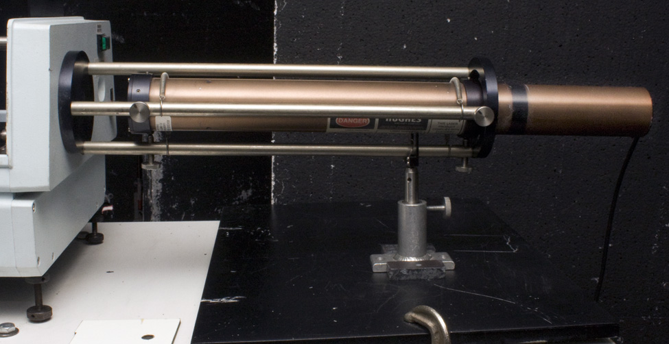
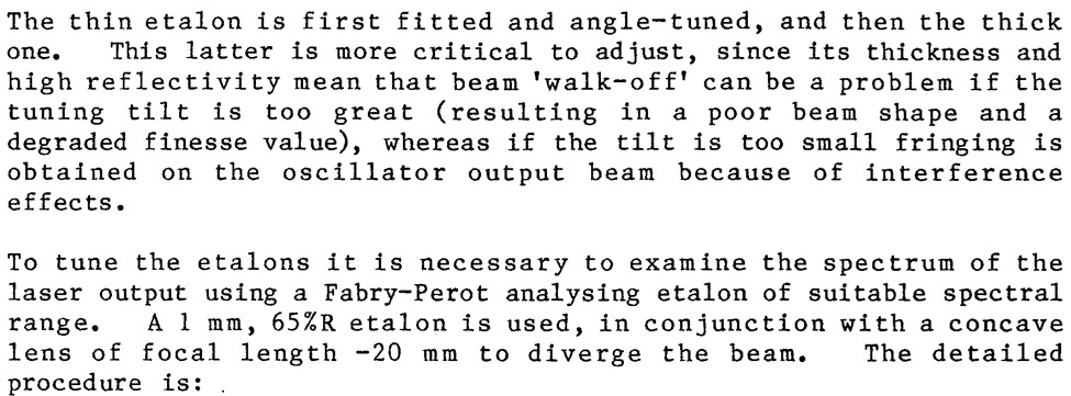
In addition to the He-Ne up the old wazoo, a 50 mW 670nm diode laser from China goes down the old gazoo, the output coupler, at the other end of the oscillator, for a suspenders and belt approach to alignment, which does pay off. This laser was mounted into a 3-D printed part, which fit nicely into a Newport MM-2 Mirror Mount, which pitches and yaws the laser. This assembly was attached to a Newport 460 XZ stage, so that it could be translated to center the He-Ne beam exiting the ruby rod right into the 800 micron pinhole in a Jodon Spatial Filter Pinhole Mount, which makes the elliptical diode beam nice and round.
This structure was mounted onto a Newport 625 Translating Stage, so the laser could be moved out of the way, without ruining its alignment relative to the oscillator when the etalons were being fitted. Once the etalons are in, and it is time to move to the spatial filter and amplifier, the 460 sub-assembly is unscrewed from the slide, with the 625 translator still screwed into the JK Optical Bed.

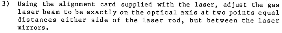
Verifying that the output mirror is wedged properly is done similarly, with the front diode laser, observing the paper target on the front it. Curiously there is only 1 reflection off out the output mirror and it goes over the head of the diode laser. Probably because a lot of the internal reflections don't come back out as the coated side is not 100% reflective.
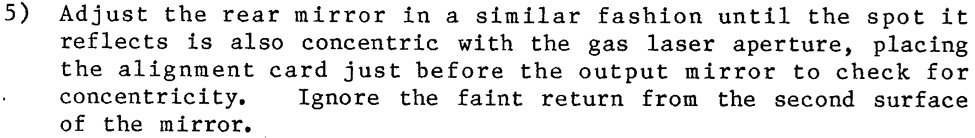
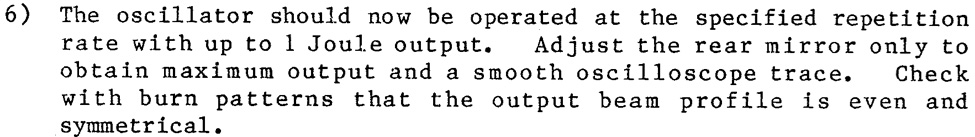
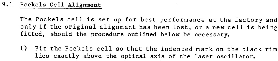
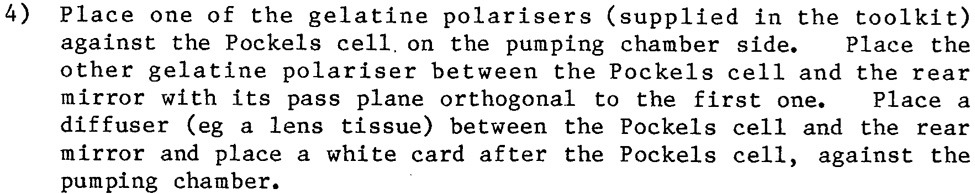
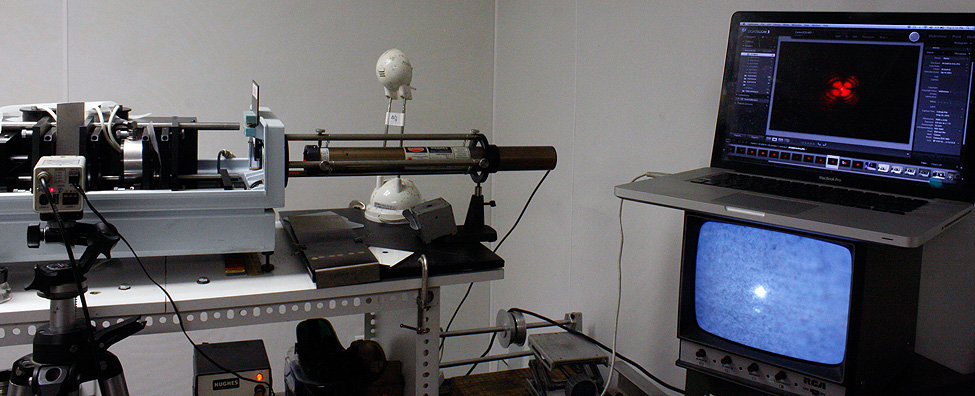
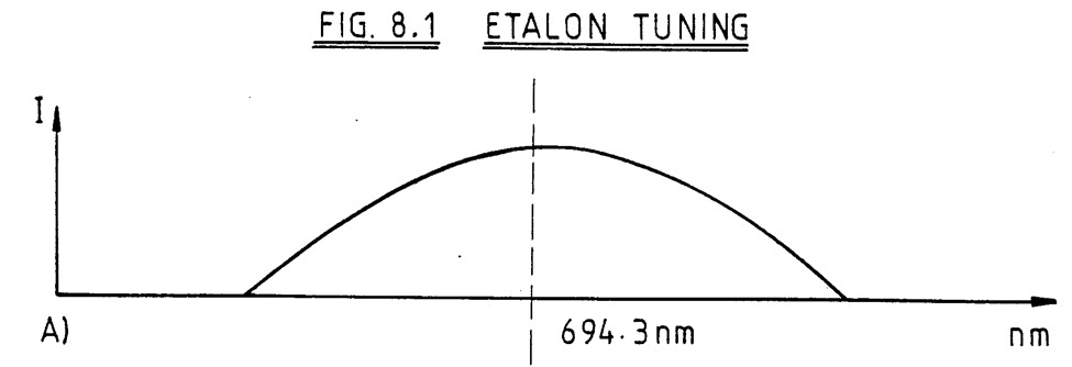
An oscilloscope is necessary, storage variety preferred. But my Kikusui Model Number COS5020-ST Storage Oscilloscope scope don't store no more. The solution is to set up a dSLR, looking at the oscilloscope screen, and hooked up to fire the JK via its PC flash connector.
Sharp-eyed viewers may notice that the camera looking at the scope screen is not a dSLR but an old Nikon film camera. But since I don't have 2 dSLR's, and need to take a digital image, I subbed a similar looking device as the model for proof of concept.
Originally the Canon 40D, the dSLR, was on the Bogen tripod mount, and would have to be unscrewed from it and then swapped over to the other photograpy station that looks at the etalons' patterns, see Section 9 below. But this unscrewing took time, and ruined the alignment of the appliances, so the scope camera evolved into the 40D's lens being clamped an antique lens holder to hold the Canon's lens in front of the scope; then the Canon body can be taken off the Nikon Bellows, and reattached to the kit lens mounted in front of the scope, and no need to waste time threading tripod sockets.
The camera shutter opens, the JK gets the signal to fire, it sends out a scope trigger, which starts the sweep, which is deflected upwards by the signal from a ThorLabs DET 210 biased detector fast photo diode. The ThorLabs detector is used as the original JK equipment doesn't want to cooperate.
The Monitor should be placed so that the aperture can be seen looking through the output coupler, as the diode laser needs to be entering the aperture to keep it on the same optical axis as the He-Ne..
Here is a gif of the oscilloscope traces as the oscillator is tuned. This may be a better approach to visualizing the state of the tune than using the stored oscilloscope traces, as the images can be scrolled through, using the dial on the back of the camera.
Typical scope and camera settings (1/22/22): Time Base, .2 msec/div; .2 V/div Channel 1, ThorLabs 210 Detector looking though JK # 6 filter (which ain't 6 ND!), Hameg HM-303 'Scope.. Canon 40D at 1/4" @ f/5.6, ISO 1000. "ScopeCamera" cardboard box built around camera/scope interface to avoid annoying glare.
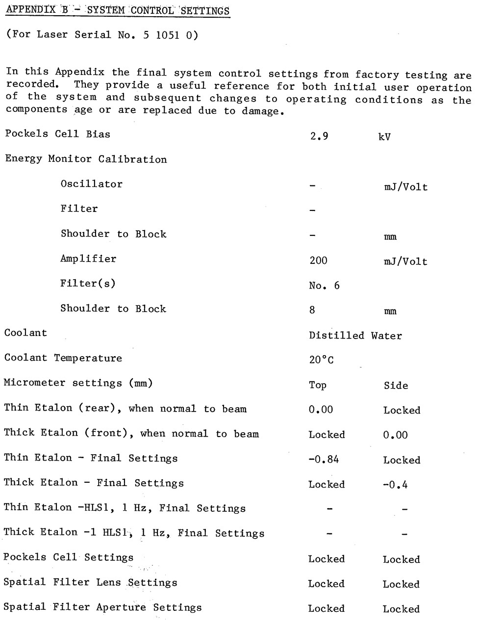
A piece of paper on the laser bed will help align the He-Ne's reflections off the Brewster Stack. Double check the alignment of the He-Ne to the ruby, plus the diode laser from the front, as the latter laser will be key to re-aligning the rear mirror after the next step.
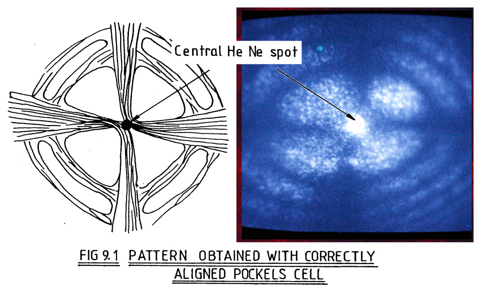
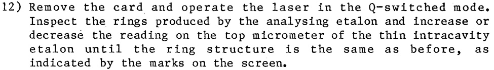
So here comes the details of Section 9.1:
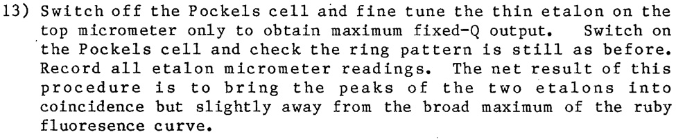
The Anait laser does not have the indented mark. But now it has red and white grease pencil markings to properly align its rotation, as outlined in steps below.
![]()
They should already be out if starting the re-alignment from scratch.

And don't forget the other laser from the front!
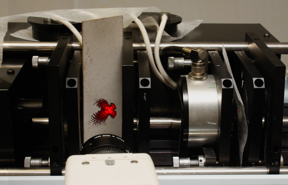
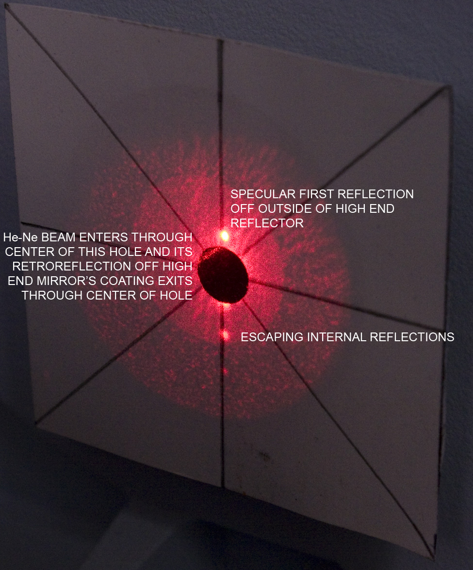
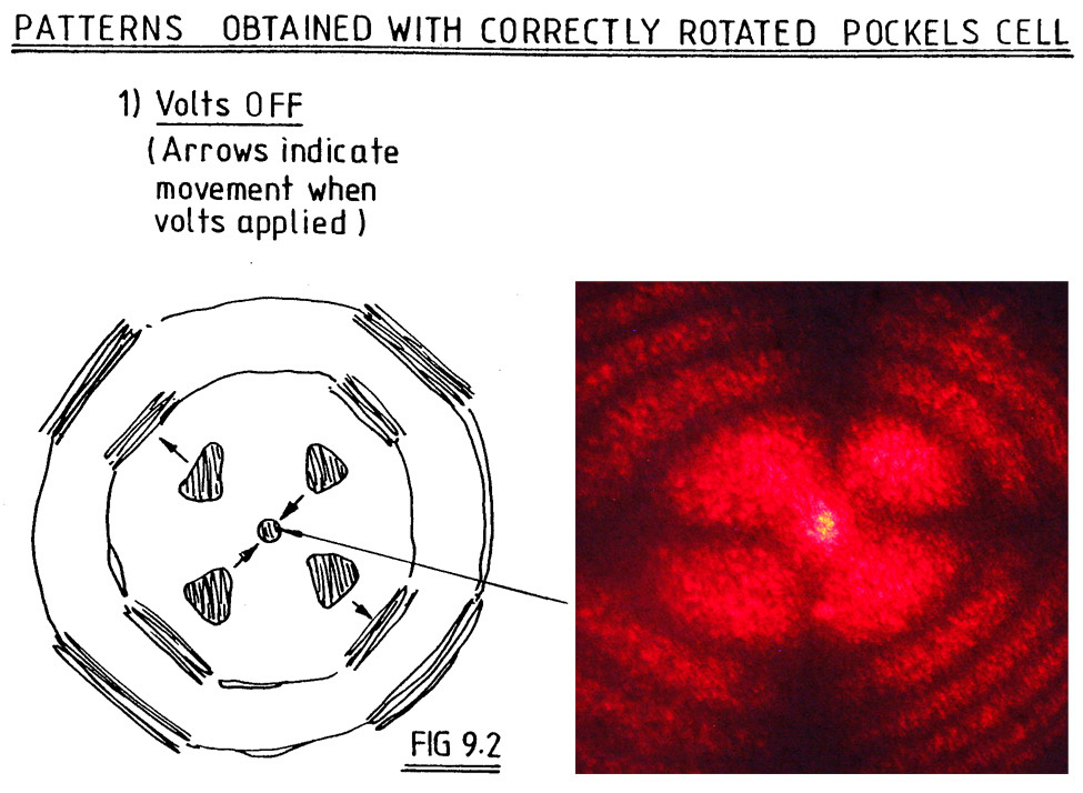
(Yes, the Maltese Cross pattern is Photoshopped in!)
This effect can me seen by either the eye, or the CCTV camera, or the dSLR. The pattern is pretty dim, so the eye needs to really adjust. Sometimes it can be so dim that the dSLR needs exposures of several seconds to record the pattern, but the pattern can really be studied, either on the camera back or on a monitor if using the camera in Tethered Capture mode in LightRoom. Surprisingly, the CCTV is sensitive enough to see the pattern in real time on its monitor, which makes alignment the easiest! Here is the Bard of Rugby's illustration, and a Canon 40D's rendering:

Not a bad idea, especially if the cell is not marked
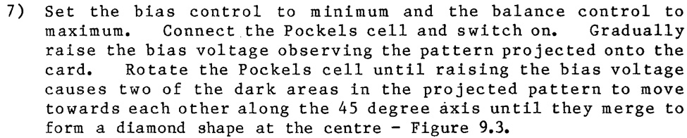
This occurs at 290 Volts on the Anait laser.

Meaning that the He-Ne central spot should be re-aligned to the Maltese Cross by pitching and yawing the Pockel's Cell Mount, in case the Cell's wobbles in its mount. Then the front entering diode is aligned once again to it. Then the rear mirror is aligned to the diode, and lasing should occur! Here are typical scope traces and burn patterns at this point.
Now back to Section 7-1:
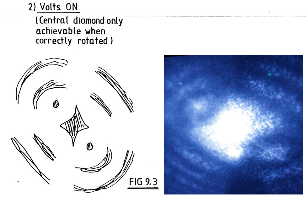
This step can be vexing, as it seems the CW alignment lasers are not a good indicator of where the ruby is entering the aperture. The reason why this happens is because the oscillator rod's ends are ground and polished to not be parallel, to avoid lasing off the interior of the rod. And the planes of grinding and polishing are not orthogonal to each other! The comparison pictures show the reflections off the rod ends of the front and back alignment lasers, and one reflection is deviating the beam in a vertical plane, like the 12:00-6:00 axis, but the other end's reflection is not in the 3:00-9:00 plane, but more like 11:00-7:00 plane, depending on which end you are looking from. So the alignment lasers get refracted through the rod on a different path than the ruby emission!
The trick then is to peak the ruby emission with the scope, and then align the He-Ne to the aperture and the burn pattern. At this stage I live life a little risky, as the black plexiglass cover has been unscrewed for quick removal to see the He-Ne going through the aperture right after the pumping chamber, and replaced with a weight on it to push the interlock switches down. The front adjusters of the He-Ne bring the beam into the aperture, and the rear adjusters put the beam in the center of the burn pattern. Once in perfect coincidence, the diode laser is realigned with the He-Ne, so all 3 lasers' path are on the same axis.
Typical scope readings and burns (1/25/22): Nice round tops at Vosc= 185 w/.2V/Div, mainly grey burns.

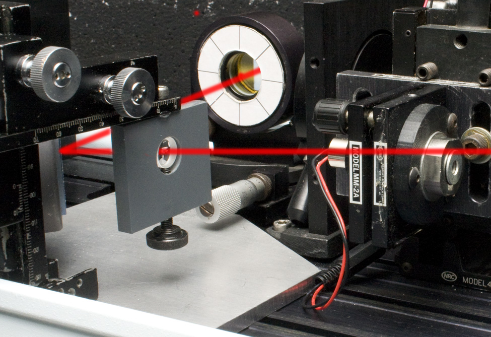
The -20mm or so lens is installed on a Microscope Slide Stage, so it can be positoned perfectly centered in the beam, and it can also be slid totally out of the beam path, for alignment purposes, not unlike the diode alignment laser, slid out of the way on its translating stage in the picture above. After the lens is a turning mirror to reflect the beam 90 degrees out of the laser head..Both the lens and mirror are attached to an aluminum plate with one corner cut off so that it can nestle agains the inside edge of the laser head and bump up against the spatial filter's lens mount.

The back of modified Modern Optics Mirror Mount is visible in this view of the etalon set up, along with the etalon in its Oriel Gimbal Mount. Taking a burn pattern before the lens, and aligning the He-Ne to it and the aperture will help getting the analyzing etalon properly positioned. But before putting the etalon in place, taking new burn patterns where the etalon assembly will go on the same piece of paper that the afore-mentioned burns were taken will level out the beam to be parallel to the laser bed by adjusting the turning mirror. Then the analyzing etalon can be inserted, and the He-Ne fine-tuned to go through its center. Burns can also be taken before inserting analyzing etalon to establish where the center of the suitable screen should go.
![]()
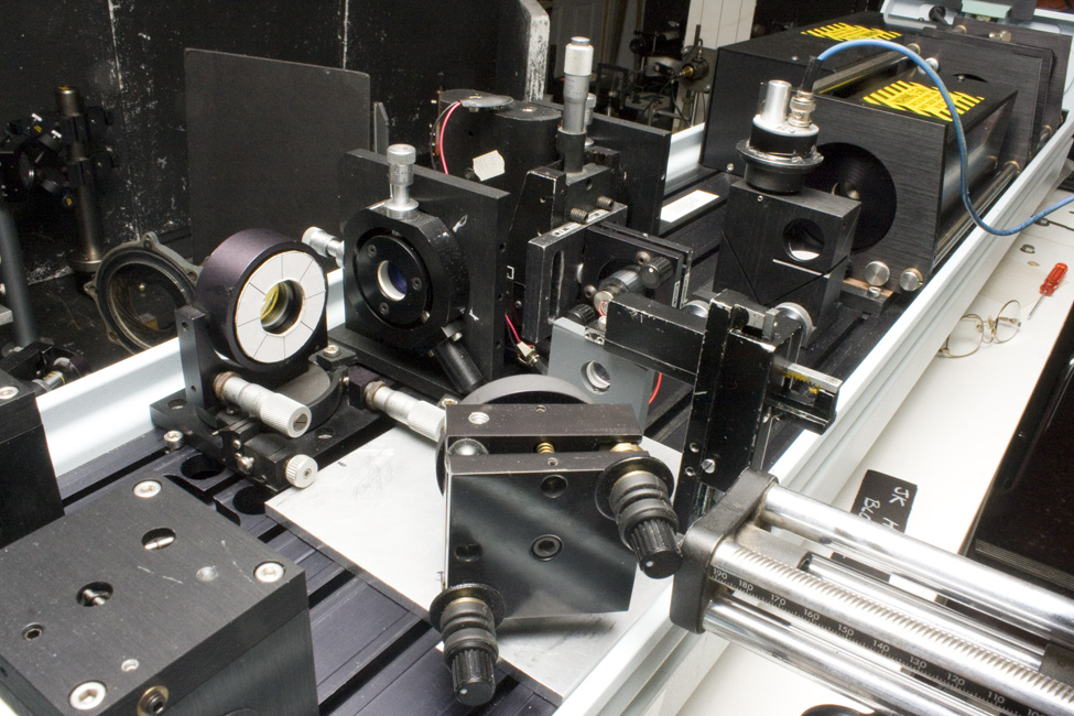
The grid is on one centimeter centers.
Not only can the lens be used, but the turning mirror, and the pitch and yaw of the etalon's gimbal mount. These rings are visualized by looking at the target with a dSLR, which triggers the laser through the camera's flash connection, like this link. The gif below was made by firing the laser, seeing the centration of the rings, adjusting an axis, firing, looking at the result, rinse and repeat until it looks as good as it can get.
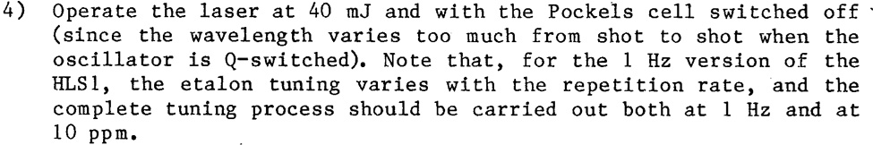
A Nikon PB-4 Bellows on a Bogen Tripod Head is C-clamped to the laser cart so that no one trips over any tripod legs on the floor. Although a Nikon N8008 is depicted below, a Canon 40D is used in the operation. An adapter is used to allow the Canon to attach to the Nikon bellows. The camera can then be simply removed from the bellows without changing the framing or the focus if and when it needs to be swapped over to the oscilloscope set up, which has the Canon's kit lens set up in front of it, as shown several pictures above. Typical exposure is 1/8" on 40D, f/8 on the Bellows Nikkor, ISO 1000 on sensor.
The 40D talks to Adobe LightRoom via Tethered Capture.
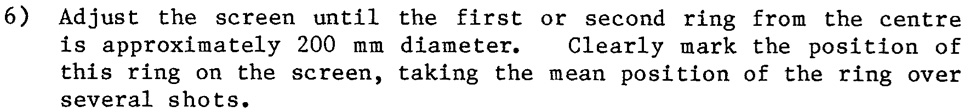
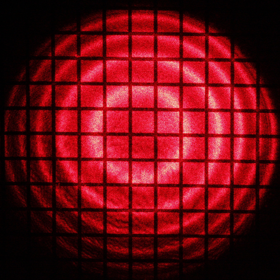
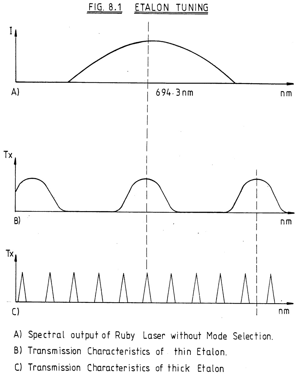
The beam profile is nicely centered. This batch of rings is with no etalons in place, so it is the result of the multitude of wavelengths being emitted, like the spectrum of Figure 8.1A.
The dSLR is connected to a laptop via the USB port. With Tethered Capture running in Adobe LightRoom (or equivalent software), pressing the shutter release on the camera in the software opens the shutter, which fires the laser just as if it were an electronic flash via the PC connector, then the camera captures the fringe pattern which exists for a blink of an eye, which then pops up on the computer screen. The fringe pattern captured as a baseline in Step 6 above can be compared with the new capture as described below in Step 9.
Not only can the etalon be placed into flash mode with the He-Ne, but what can make it quicker is to slide the diode laser back into position, align both lasers to each other, with the aperture as the pivot point. Taking the black plexi lid off the pumping chamber to inspect the aperture is a good idea. Don;t forget ti doesn't charge when that cover is off!
Here are some typical readings: V osc = 190, En Mon = 2 div's @ 20mV/div.
Using the Compare View in Adobe LightRoom (or equivalent program) the baseline fringes can be held in the Select Side of the screen, and the shots fired as in 9) above can be compared on the candidate side with the non-etalon equipped photograph. Fire the laser, examine the pattern, turn the micrormeter a bit, fire the laser, if that don't do it, turn the mic again, rinse and repeat until the size of the fringes match.

Step 11) is similar to 9), and it helps once again to put the diode laser in the loop to find the flash position. Sometmes you can do it just iwth the rear laser. But don't forget to put some burn paper in front of the diode laser before continuing! Otherwise you know what can happen!
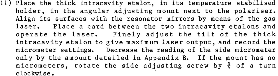
In the case of this laser, the amount is -.4mm. Here is a survey of etalon tilts and other service settings for a few other HLS lasers.
It is a testimonial to whoever tuned the unit in at the factory, using only marks on a card, and no dSLR as a crutch! In the current state of this tune, the thin etalon tlt is -82 for best perfomance I could get, as opposed to the Bard's 84! Thick etalon is at -40. So if one is in a hurry or doesn't have all these cool toys, defaulting to the manufacturer's data could be successful.

It's a snap!
The next step is tuning the spatial filter. The Service Manual for this laser in its Section 11.1, HLS2 Amplifier Alignment, details installing the turning mirors, lens, and pinhole. But since they are already installed, steps 1) through 10) are skipped in this discourse.
Remove the energy monitor from its position after the oscillator, as the beam sampling plate in the monitor skews the beam coming out of it significantly! But instead of using it as detailed below after the spatial filter, put a white card at the entrance hole of the amplifier assembly, and photograph the spatially filtered beam.

Fire, move knob, fire, move knob, until the spot is nice and round. Almost as easy as tuning the spatial filter with a continuous wave laser!
Centering the spatially filtered divergent beam through the amplifier rod can be painless if a diffuser is placed at the output of the laser and the camera looks at it from the side opposite the laser. The projection of the oscillator’s light through the rod shows when it is centered, thanks to moving the spatial filter’s lens and pinhole micrometres the same amount. Then the laser is ready to have its amplifier turned on.