Spurred on by conversations on the Holography Forum, (http://holoforum.org/forum/viewtopic.php?f=11&t=662) I decided to check the coherence of some of my workhorse lasers. Traditionally the set up for a coherence length hologram was in the transmission mode. Back at the first reports of coherence length holograms, circa 1967, there were no really good silver halide holographic recording materials capable of recording decent reflection holograms. Plus the transmission hologram case relaxes the vibration requirement with its lower spatial frequency, and with an unbleached hologram it can be the thriftiest with light.
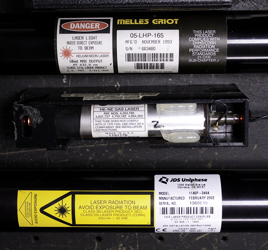
Three functioning Helium Neon lasers were chosen from my museum for the survey: Unphase 1145P, Melles Griot 05-LHP-165 and a Uniphase 1 mW, whose model number is hidden behind the side walls of its enclosure. Also tested were a Coherent Compass 315M, and a Melles Griot BLD 605, both of which are of the Diode-Pumped Soid State persuasion.
But now there are better silver halide plates, and I decided to try making a SBR hologram of the coherence length bar. This should be a nifty set up, as the plate would be the zero point of the measurement. The depth that can be seen in the scene, multiplied by 2, times the cosine of the angle the bar makes with the holographic plate would be the coherence length of the laser. Nothing could be easier!
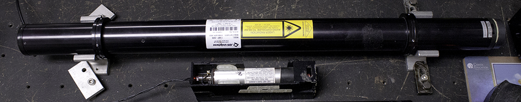
The cylindrical lasers were held on the table with vee-blocks, so that they could be interchanged easily without disturbing the set up. Fortunately the littlest He-Ne, the 1 mW Uniphase, had its output at approximately the same height above the table, so it too readily fit into the set up.
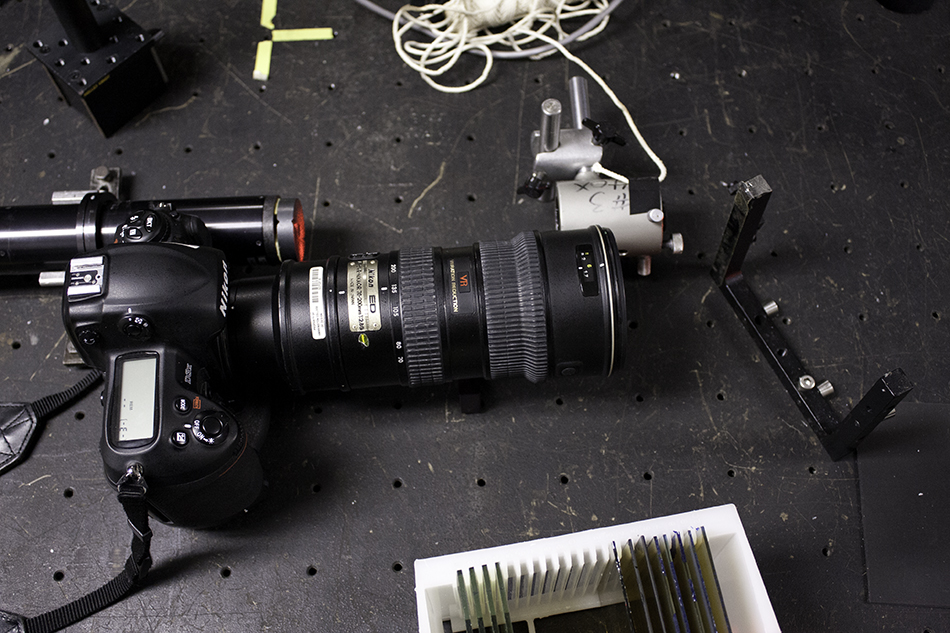
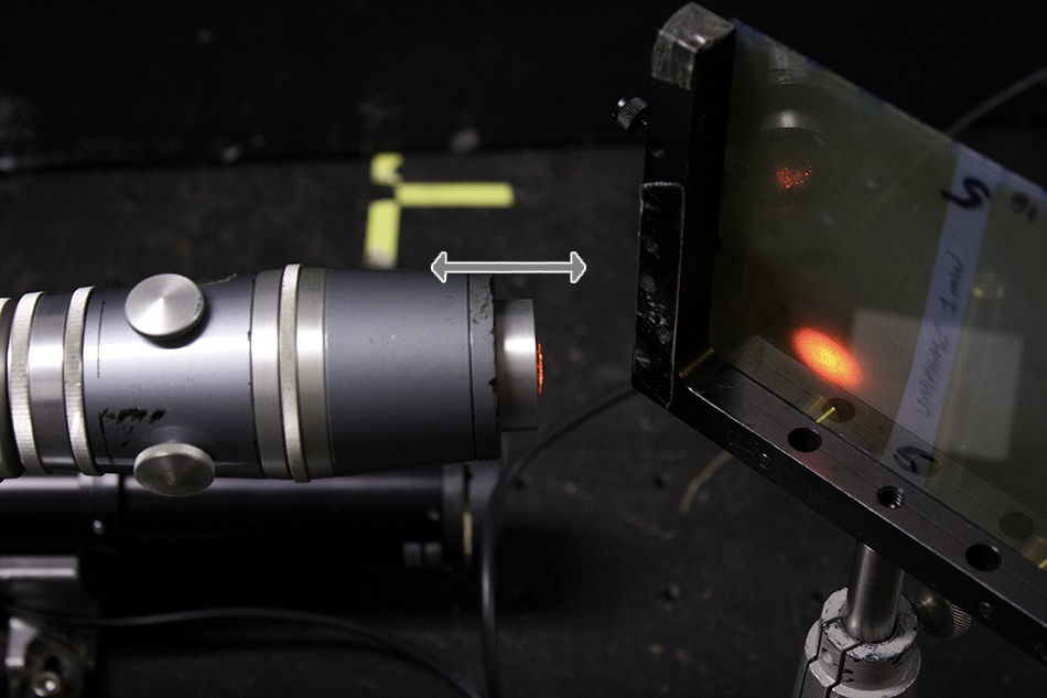
The laser’s beam was spread with a Gaertner Spatial Filter, and the plateholder was placed where the beam just filled a 4” by 5” plate, tilted at Brewster’s angle for the maximum throughput of light to the coherence length bar, with the laser’s polarization correspondingly oriented. The bar was tilted so that its complete length could be seen through a camera viewfinder framed by the plateholder for later analysis. The bar just touched the holographic plate in the plateholder, so that was Ground Zero.
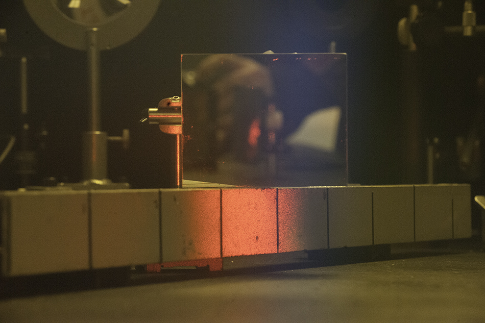
Here is the plateholder and the Coherence Length Bar, which is a piece of angle iron covered with Scotchlite contact paper. Scotchlite, registered trademark of 3M, has tiny glass beads embedded in it to give it retroreflective properties a la Dew Heiligenschein, (Google or Wikipedia that one!), and is typically used on street signs to make them glow very brightly when headlights hit them at night. Even though the spatially filtered light is incident at close to grazing incidence on the Bar in this set up, an amazing amount is retroreflected toward the spatial filter and the plateholder next to it.
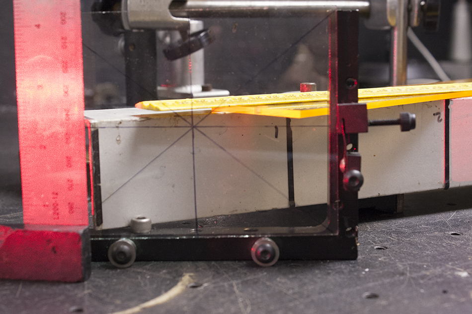
Exposures were made on Slavich PFG-01 plates of unknown heritage. The first one was done with a Uniphase 1145P purchased from Phil Bergeron of Holography Forum dot com fame. The plate was processed with CWC2 and PBQ bleach which gives an exact laser color replay with this material. The plate was replaced in the plateholder, so exactly that you can see some real time interference fringes at the edge of the bar in the picture below.
But the hologram was very noisy! Although the bar was kicking back a lot of light to the holographic plate during exposure, a lot of that was not coherent with the reference beam and simply fogged the plate, making the bar look like it was in a snow storm. Or the plates were fogged to begin with. Plus they are not that great either. The alignment procedure took into account photographing these holos so they can be published or uploaded. However, it is very hard to see what is going on in there when the coherence fades in and out, depth of field issues, photographic exposure times, etc., so the setup was re-configured to a transmission mode. Those ancient holographers did know what they were doing!
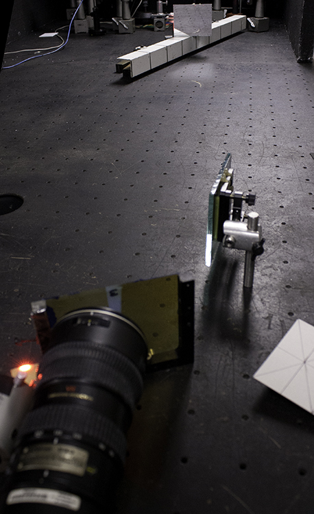
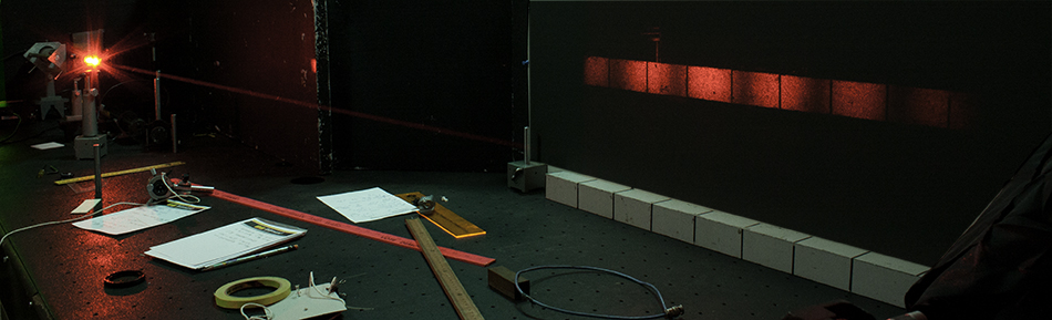
The bar was moved further away, lit up from end to end with spatially filtered light, and once again it could be seen in its entirety through a camera viewfinder that was placed behind the plate holder, which was placed next to the spatial filter. This position was chosen so that as much of the retro-reflected light from the coherence bar, heading to return to the spatial filter, would also scatter onto the holographic recording plate.
Below is the set up looking over the shoulder of the camera.
Once the view through the plateholder was determined, the distance from the spatial filter to the center of the bar was measured with a string,
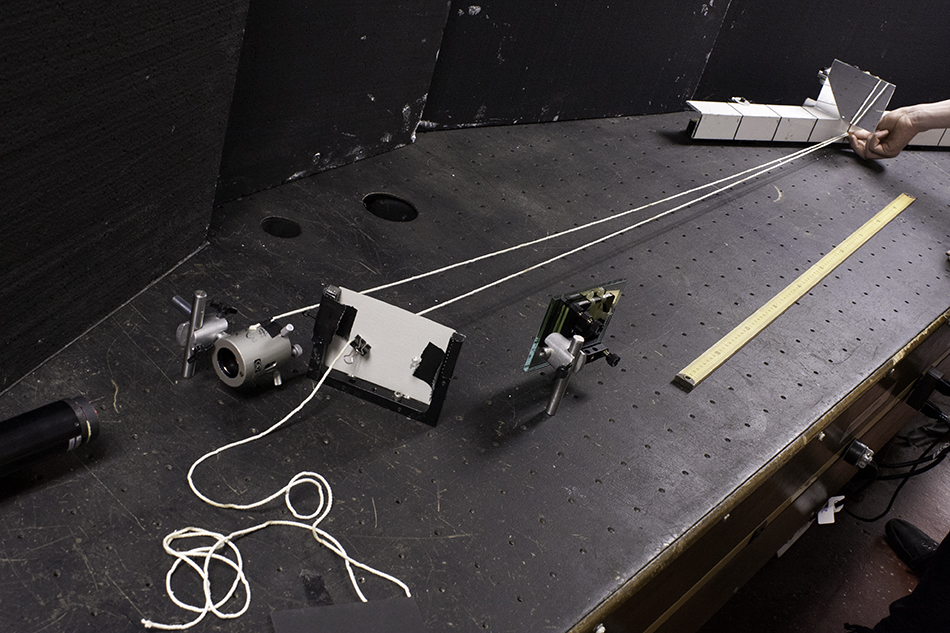
and the reference beam path via a pair of mirrors was configured to match that distance and to have the beam arrive at the plate at 45 degrees from the normal.
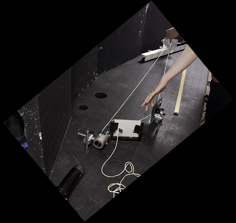
Only half of a 4” by 5” plate was lit by the reference beam in this configuration, which is a feature, not a bug, as two different exposures could be shot on the same plate, as the exposures were on some antique Agfa 10E75 and the times were best guesstimates.
Because the volume to be holographed was substantial, so were the exposure times, in the order of a couple of minutes for the mighty 1 milliWatter. But because the set up was on a nice heavy Modern Optics table with 50 mm thick styrofoam insulation surrounding it to eliminate wind currents there were no movement problems.
Photographing these holographic virtual images through the plate was daunting. There is a trade off between speckle size and depth of field. Smaller lens opening, greater depth of field to see more of the bar in focus, however the speckle gets chunkier.
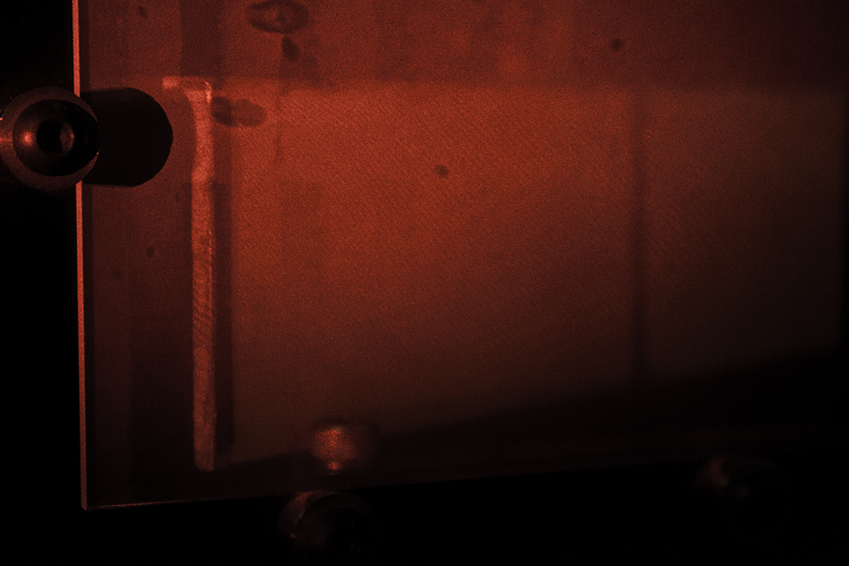
In this shot, the camera is looking through the coherence length hologram of the Uniphase 1145P, (notice the pyrogallol yellow staining of the PyroChrome processing) with the room lights on weakly. Although the bar was completely illuminated front to back, only a decimeter on either side of the zero path length point is recorded, as the rest of the light was not within the coherent path length envelope of the laser.
But in the laser only lit photo below, you can sort of see there is a bright zone where path lengths are equal, and fades out on either side of it. It returns slightly, not as bright as that sweet spot in the center of the bar.
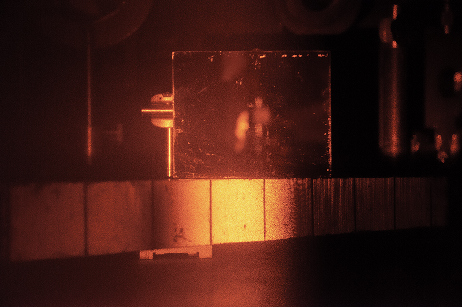
It has to be admitted that the above photo is a Photoshop composite of two exposures. The far end of the bar did not come out in the lesser camera exposure, and in a greater exposure the near side was almost completely saturated. These details are visible to the human eye, whose “auto-exposure” mechanism enables us to see into the almost shadows. Notice the out of focus image of the plateholder and camera reflected in the reference mirror above the bright patch.
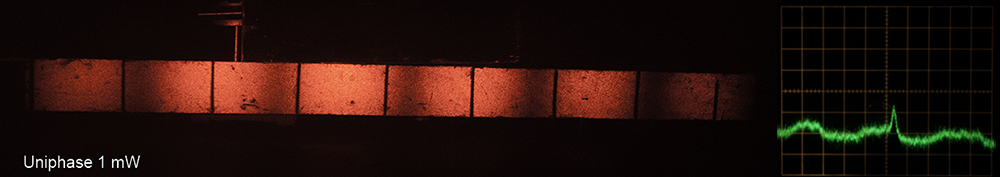
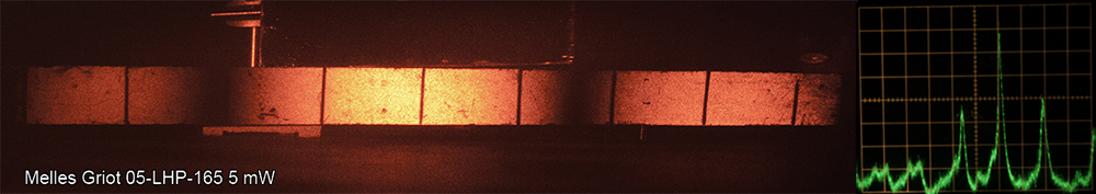
With the 1145P illustrated above, there is a bright area, which fades to the left and right, then slightly returns on either side. With the M-G 5 mW, the picture is essentially the same in the middle, but the coherence returns on the side lobes just as bright as in the center and extends to either end of the bar. The 1 mW has a smaller band of coherence, which keeps repeating! But because these digitally photographed virtual images don’t do justice to what the eyes see through the holographic plate, a different approach was taken to present them, using the holographic real image.
Everyone is familiar to some degree with flushing out the real image of a transmission hologram by pointing an undiverged laser beam through it, in the opposite direction of the recording reference beam. This approach was tried with these images, however due to the very high f/number of this configuration, the speckle was way too big.
A diffraction-limited laser beam shaping telescope, the Spectra-Physics 332 Spatial Filter plus Collimating Lens made a 20 mm diameter replay beam that not only cut down speckle substantially, but by thanks to the focusing mount which could not only collimate the output beam but converge it at the same distance from the plate as the reference beam path, a true, undistorted real image could be conjured up.
And as a bonus, a type of holographic Scheimpflug could be used, by focusing the real image on a matte board. With proper focus of the beam shaping telescope and positioning, an image was projected that was exactly the same size as the Coherence Bar, which you can see on the table in front of the poster board!
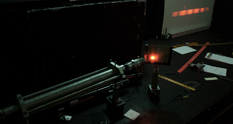
Above is the real image set up from the left, and below is the real image set up from the right, albeit with a little Photoshopping to show the set up and the image (of the coherence of the 1 mW Uniphase laser) to their best advantages. This set up yielded the clearest photos of the bar.
It is easily seen how the coherence comes and goes with the smaller lasers, and tries to come back.
After the lasers had their coherence pictures taken, they were put on the scanning Fabry-Perot Interferometer Spectrum Analyzer. This device has a Spectra-Physics 470 head, driven by a Jodon/Eldon box, wired up to a Kikusui Oscilloscope. Before the beam enters the head, it passes through a half-wave plate followed by a polarizing beamsplitting cube, the basic beamsplitting configuration. This arrangement was put in place to attenuate the beam before it enters the Spectrum Analyzer, to be able to equalize the power, as I wanted to keep all the settings on the ‘scope and driver the same for all the different outputs of the three He-Ne lasers.
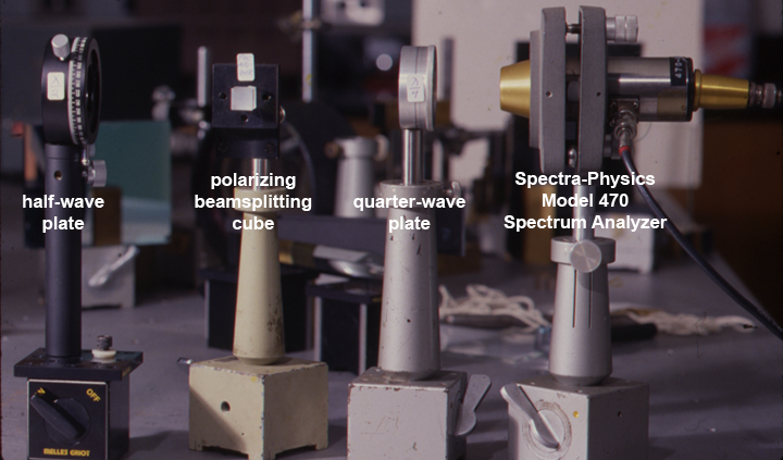
After the beamsplitting cube a quarter wave plate was introduced, to circularly polarize the beam as part of an optical isolation circuit. Any beams going back into the laser cavity could cause feedback that would spoil the spectral analysis.
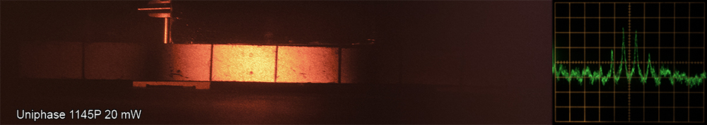
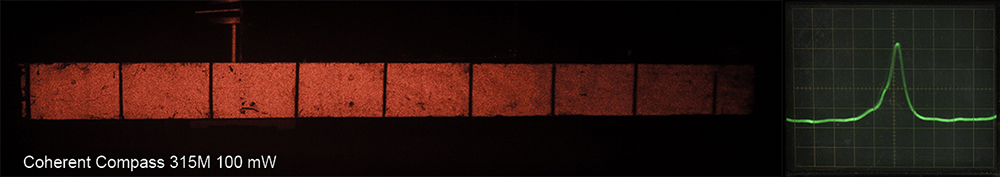
Here are the ‘scope traces for the three He-Ne’s and the Compass, paired with the images of the bar from their coherence length holograms, all settings being equal. (Except the 315M’s trace, which was done on a different day.) The BLD 605's hologram and oscilloscope trace looked the same as that of the 315M's, so it is not included.
Here is a table of the coherence lengths of the above lasers, as measured with the string method detailed above:
|
LASER |
POWER |
MEASURED COHERENCE |
NODE TO NODE DISTANCE |
|
Uniphase |
1 mW |
19 cm |
23 cm |
|
Melles Griot 05-LHP-165 |
5 mW |
43 cm |
70 |
|
Uniphase 1145P |
21 mW |
34 cm |
52 cm |
|
Coherent Compass 315M |
100 mW |
> 3 m |
N/A |
|
Melles Griot BLD-605 |
400 mW |
> 3 m |
N/A |
Very interesting! In the table, there is a difference between the complete loss of coherence, the node to node distance, versus what could be used for recording holograms, the measured coherence.
The Coherence Bar is marked every decimeter, or 10 centimeters. The string method detailed above was used to arrive at the measurements in the table, which are approximately twice the length of the bright bars in the holograms, as the measurement subtracts the near path length from the far path length of spatial filter to bar to plate holder. This technique automagically takes into account the cosine factor from the angle the bar makes with the holographic plate. Accuracy of the measurement is within a centimeter.
Every effort was made in this experiment to keep everything as consistent and reproducible as possible. Sometimes you can be pleasantly surprised by results! Or annoyed, as the conventional wisdom predicts a shorter tube gives greater coherence, which is not the case of the dinky 1 mW’er observed here!
It would be great if other holographic experimenters were to attempt this test to confirm or deny my results.